Cymbal with low fundamental frequency

a technology of fundamental frequency and cymbal, which is applied in the field of percussion instruments, can solve the problems of not having the qualities expected in a precise dome and little resistance to deflection

Inactive Publication Date: 2009-04-30
STANNARD JOHN
View PDF0 Cites 8 Cited by
  • Summary
  • Abstract
  • Description
  • Claims
  • Application Information

AI Technical Summary

Problems solved by technology

It offers little resistance to deflection and none of the qualities expected in a precise dome.

Method used


Image

  • Cymbal with low fundamental frequency
  • Cymbal with low fundamental frequency

Examples


Embodiment Construction

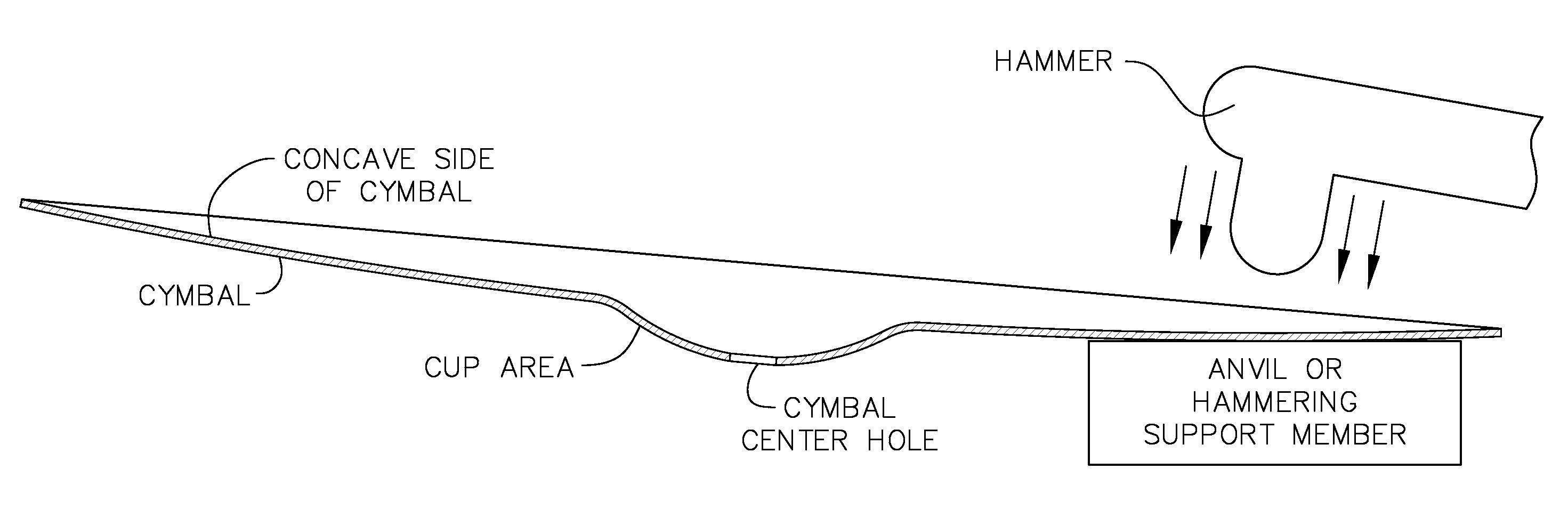
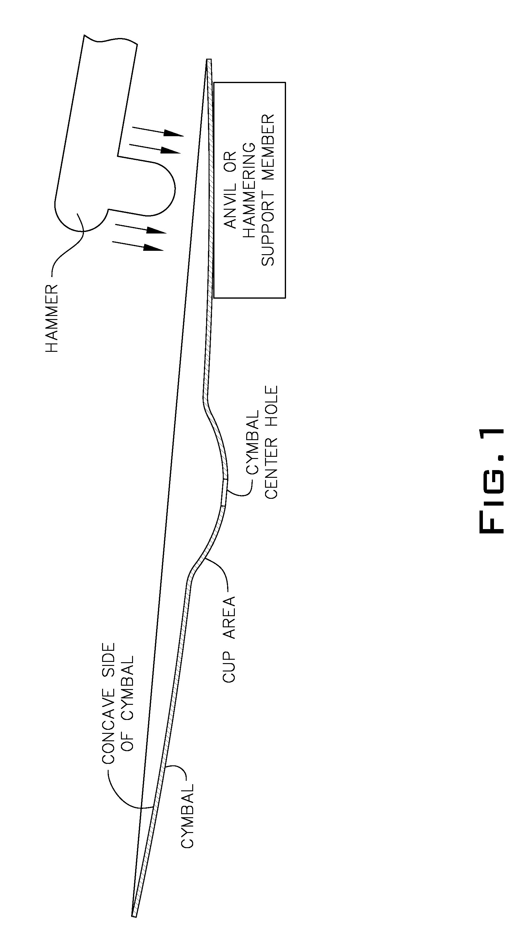
[0022]To make this invention, the structure of the cymbal must be altered in a way which reduces the inherent stiffness of the dome-shape of the cymbal. As generally depicted in FIG. 1, one example of how to make the present invention is by continuingly or significantly hammering the concave underside of the cymbal (after the main shape of tie cymbal has been formed) in a manner which forms dents in the surface of the cymbal. The cymbal can be made by continuingly hammering the concave underside of a pre-formed cymbal in a manner which forms dents in a surface of the cymbal until a structural integrity of the cymbal is reduced to a point where a fundamental frequency vibration causes a considerable vibrato and / or phase shifting effect. Such hammering requires a backing surface on which the cymbal will be supported during hammering. This backing surface can be of a hard material such as steel, or a softer material such as hard wood. The backing “block” should be of sufficient strengt...


PUM


Abstract

A cymbal where the lowest frequency mode of vibration in the cymbal is less than 20 cycles per second, and where the lowest mode is of a great enough amplitude to be capable of producing a prominent vibrato effect and a prominent phase shifting effect when said cymbal is struck, the cymbal being made by hammering a concave underside of a pre-formed cymbal in a manner which forms dents in a surface of said cymbal.

Description

RELATED APPLICATION[0001]This application claims the benefit of U.S. Provisional Patent Application Ser. No. 60 / 983,360 filed Oct. 29, 2007.FIELD OF THE INVENTION[0002]This invention relates to percussion instruments, in particular cymbals with low fundamental frequencies.[0003]1. Background of the Invention[0004]By way of background to further understand the invention described hereinafter, the following definitions are provided:[0005]Phase Shifting: A term commonly used in modern music recording whereby the overtone structure of a sound such as a musical instrument is modulated in a manner which periodically cancels frequencies in a cascading and repeating pattern. Examples are rotating speakers such as the “Leslie” electronic digital phase shift equipment and “flanging” signal processing equipment. A similar effect can be achieved by suspending an instrument such as a gong, and striking the gong while it is rotating.[0006]Overtones: Overtones can be heard as simpler or individual...

Claims


Application Information

Patent Timeline
Patent Type & Authority Applications(United States)
IPC IPC(8): G10D13/06G10D13/063G10D13/24
CPCG10D13/06G10D13/063G10D13/25G10D13/24
Inventor STANNARD, JOHN
Owner STANNARD JOHN
Why Eureka
Try Eureka