
Shadow-free cove light

Inactive Publication Date: 2009-05-21
SPI LIGHTING
View PDF9 Cites 16 Cited by
  • Summary
  • Abstract
  • Description
  • Claims
  • Application Information

AI Technical Summary

Benefits of technology

[0008]Therefore, it is one object of the present invention to provide a cove lighting fixture that provides a relatively uniform backlighting of a wall absent dark spots typically associated with the electrical sockets.
[0010]It is yet another object of the invention to provide a reflector assembly for a cove lighting fixture that can be factory installed without requiring in-field adjustments during the life of the light fixture.

Problems solved by technology

This can create dark spots in the backlighting of the back wall of the cove.
However, staggering the light fixtures is generally considered an inefficient solution.
Additionally, for narrow coves, it may be difficult to install the light fixtures in a staggered arrangement.
Thus, the effectiveness of the kicker reflector is reduced over the life of the fluorescent tube.

Method used


Image

  • Shadow-free cove light
  • Shadow-free cove light
  • Shadow-free cove light

Examples


Embodiment Construction

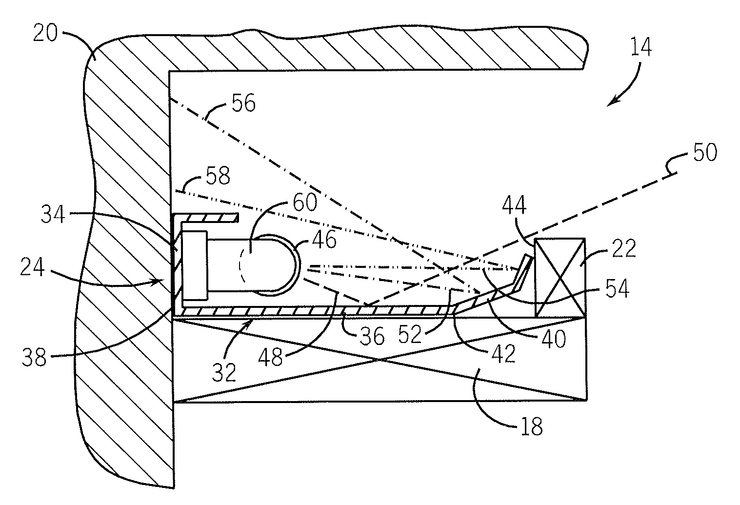
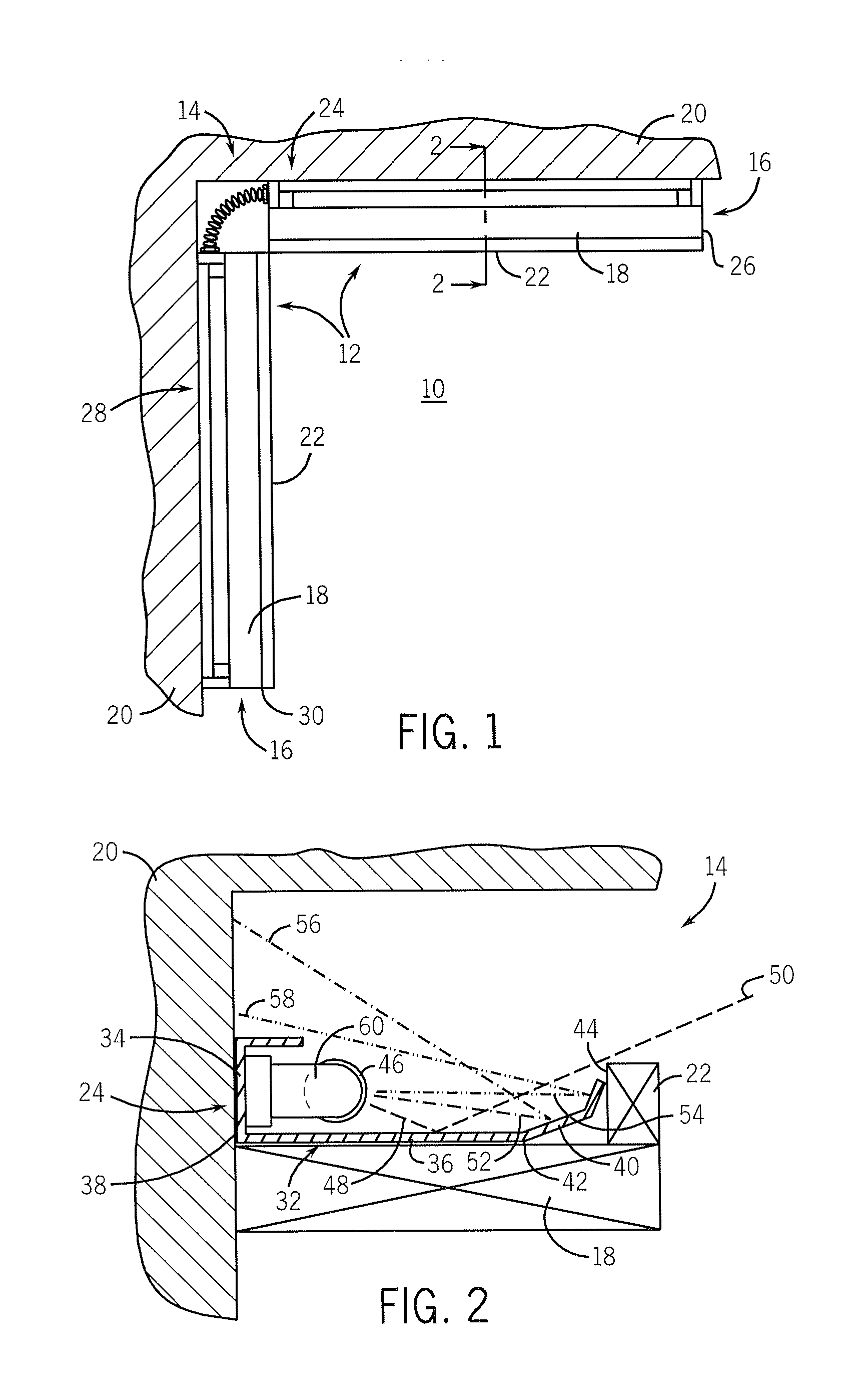
[0020]The present invention will be described with respect to light fixtures having elongated light tubes and arranged in a linear fashion to illuminate a room 10. In one preferred embodiment, the light fixtures, collectively designated 12, are positioned in an architectural cove 14, partially shown in FIG. 1, formed above the space or room 10 to be illuminated. As well-known in the art, in addition to the aesthetics that an architectural cove 14 may provide, the cove 14 provides a recess 16 in which the light fixtures 12 can be positioned and thus hidden from view. The architectural cove 14 is generally defined by a floor 18 that supports a back wall 20 and a front wall 22. The front wall 22 has a height less than the back wall 20 and thus allows light illuminated from the fixtures 12 to exit the recess 16 and provide indirect and diffused lighting of the room 10.

[0021]The light fixtures 12 are arranged, in a preferred implementation, so as to be positioned against the back wall 20...


PUM


Abstract

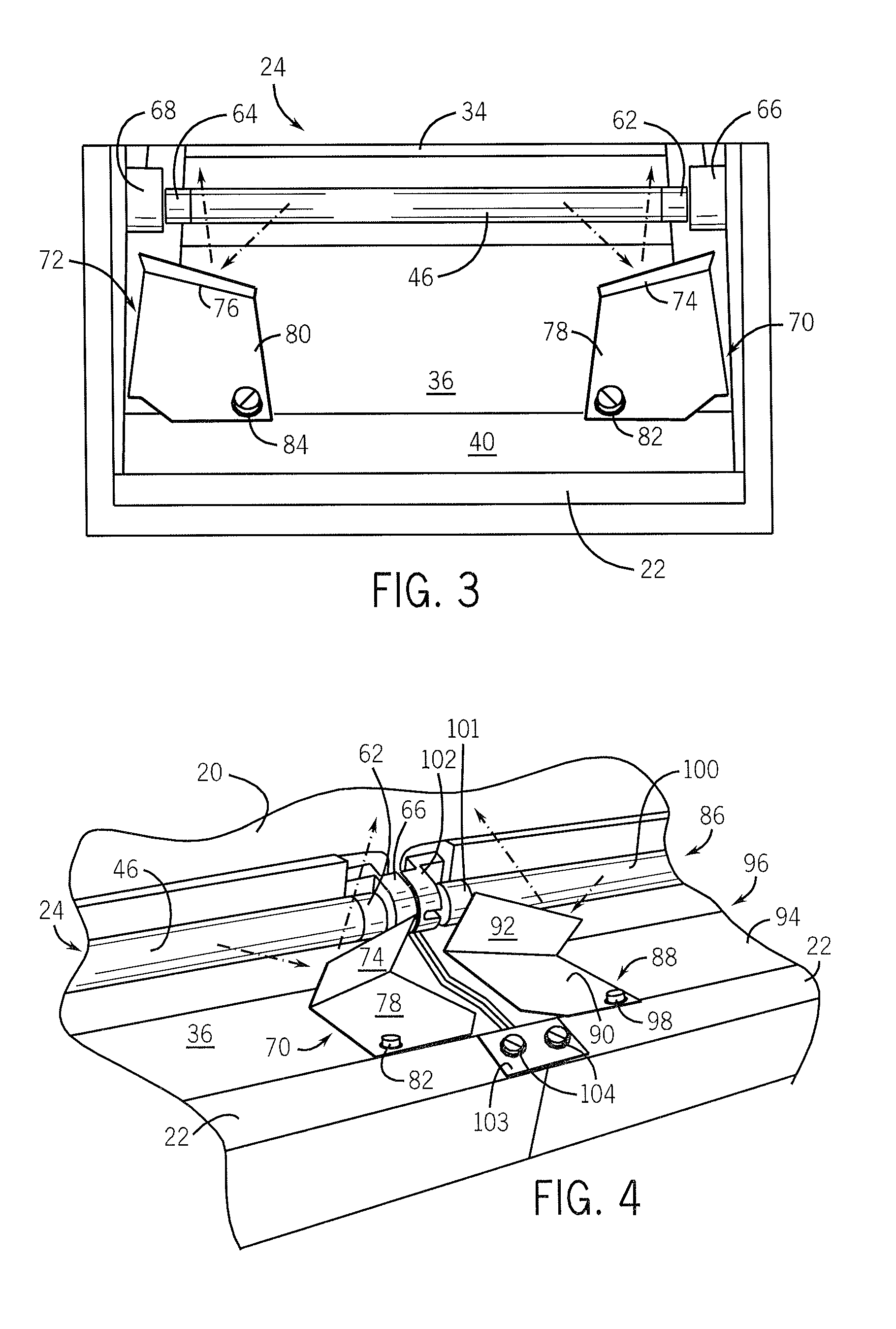
A light fixture, particularly adapted for cove lighting, includes an angled reflector assembly that directs light from a fluorescent tube generally toward the back wall of a cove that is above the electrical sockets of the light fixture. The angled reflector assembly is designed such that light is directed from the main illumination portion of the fluorescent tube, rather than from the cool spots of the fluorescent tube. The light fixture reduces dark spot formation in the backlighting of the back wall and therefore provides a relatively even illumination pattern.

Description

BACKGROUND OF THE INVENTION[0001]The present invention is generally directed to lighting systems and, more particularly, to a light fixture to be used in a recessed manner, such as in an architectural cove, to provide generally shadow-free backlighting of a wall so as to indirectly illuminate a space or room.[0002]In addition to their aesthetic features, architectural coves also provide a recess in which lighting systems may be installed to indirectly illuminate a space, such as a bedroom or hallway. Conventional cove light fixtures are installed either end-to-end in a single row or in a pair of staggered or overlapped rows along or proximate the back wall of the cove.[0003]Cove light fixtures typically use elongated fluorescent tubes as the light source. The tubes are coupled between a pair of sockets to electrically connect the tube to a power source. The sockets are generally in-line with the tube and thus form a non-luminous feature at each end of the light fixture. When arrange...

Claims


Application Information

Patent Timeline
IPC IPC(8): F21V7/04
CPCF21S2/00F21V7/005F21S8/037F21S8/033F21Y2103/00
Inventor WITTIG, JEREMY J.
Owner SPI LIGHTING
Learn More