Piezoelectric vibrating reed, piezoelectric vibrator, oscillator, electronic device, wave clock, and manufacturing method of piezoelectric vibrating reed

a manufacturing method and piezoelectric technology, applied in piezoelectric/electrostrictive transducers, generators/motors, devices material selection, etc., can solve the problems of terminals easily undergoing deformation, terminals may no longer be able to ensure electrical independence, etc., to save power and improve performance.

Inactive Publication Date: 2009-06-18
SII CRYSTAL TECH
View PDF9 Cites 4 Cited by
  • Summary
  • Abstract
  • Description
  • Claims
  • Application Information

AI Technical Summary

Benefits of technology

[0047]According to the oscillator, the electronic device, and the wave clock of the invention, because each includes the piezoel

Problems solved by technology

With a type using two lead terminals as before, even when the diameter of the lead terminals is reduced, the rigidity deteriorates extremely and the lead terminals readily undergo deformation.
The lead terminals therefore may no longer be able to ensure electrical independence.
Incidentally, the piezoelectric vibrating reed in the related art has a disadvantage that the R1 characteristic (series resonance resistance value) undesirably becomes higher when config

Method used


Image

  • Piezoelectric vibrating reed, piezoelectric vibrator, oscillator, electronic device, wave clock, and manufacturing method of piezoelectric vibrating reed
  • Piezoelectric vibrating reed, piezoelectric vibrator, oscillator, electronic device, wave clock, and manufacturing method of piezoelectric vibrating reed
  • Piezoelectric vibrating reed, piezoelectric vibrator, oscillator, electronic device, wave clock, and manufacturing method of piezoelectric vibrating reed

Examples


first embodiment

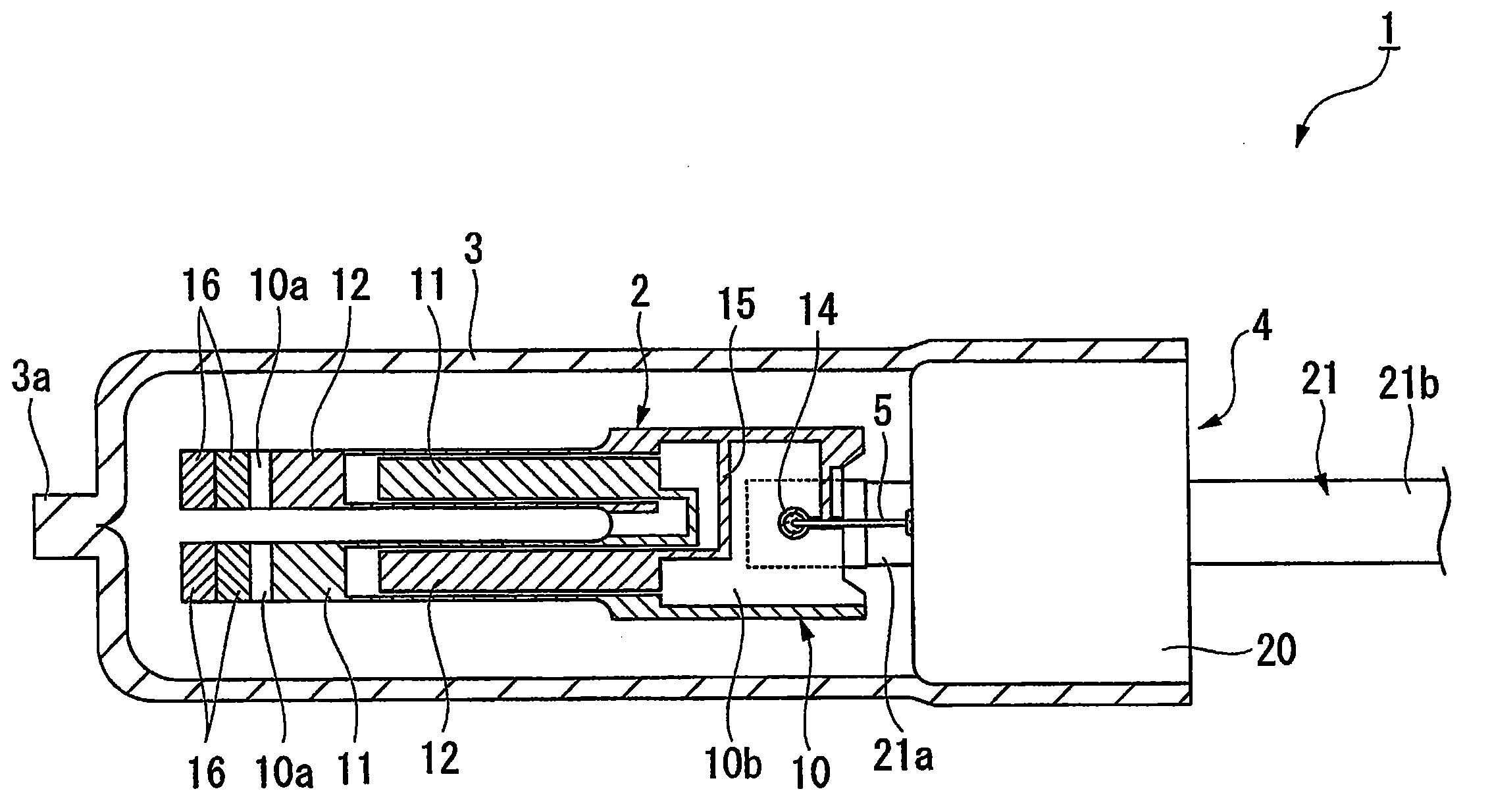
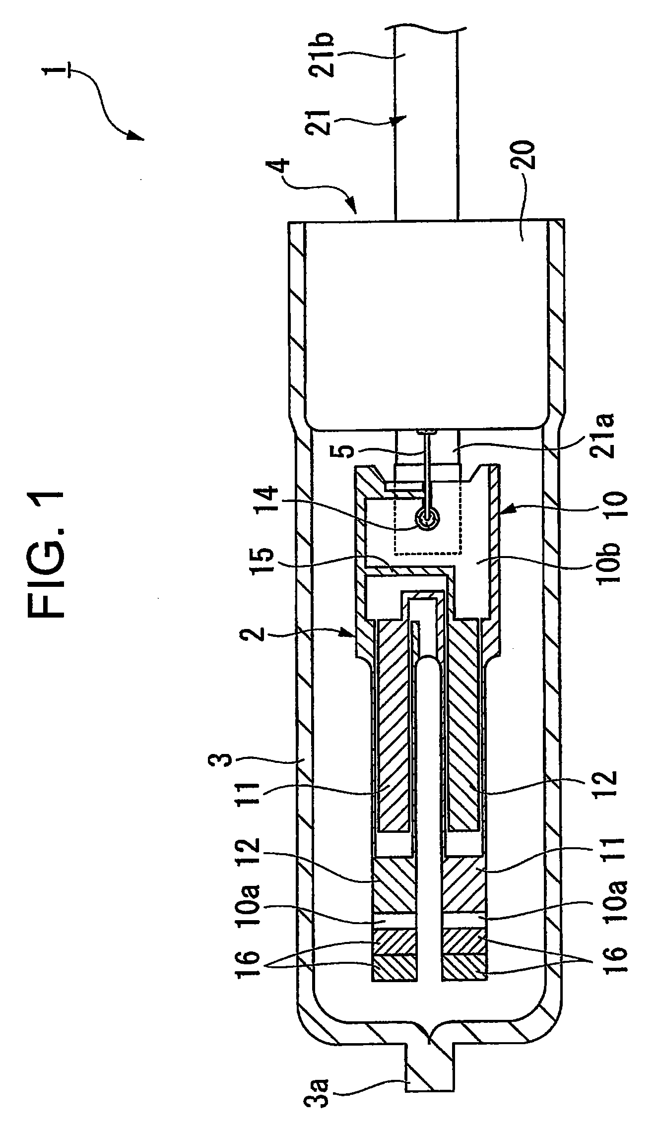
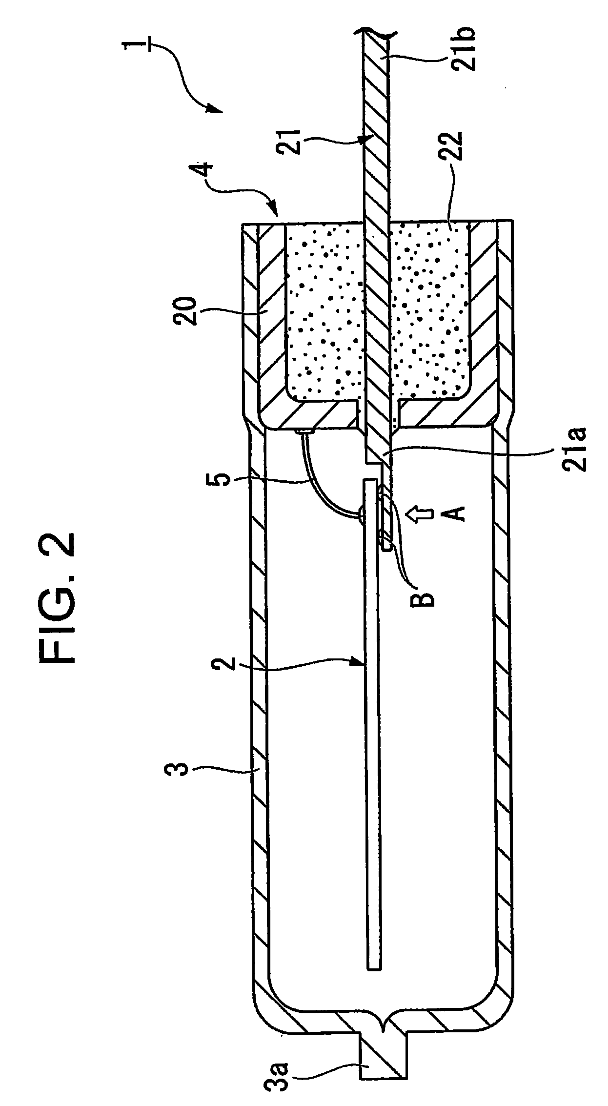
[0079]Hereinafter, a first embodiment of the invention will be described with reference to FIG. 1 through FIG. 12. In this embodiment, descriptions will be given to a piezoelectric vibrator of a cylinder package type having a single lead terminal by way of example.

[0080]As are shown in FIG. 1 through FIG. 12, a piezoelectric vibrator 1 of this embodiment includes a piezoelectric vibrating reed 2, a case 3 that accommodates the piezoelectric vibrating reed 2 inside, an airtight terminal 4 that hermitically seals the piezoelectric vibrator 1 inside the case 3, and a wire (wire rod) 5 that electrically connects a stem 20 and the other mount electrode 14 described below inside the case 3.

[0081]As are shown in FIG. 4 and FIG. 5, the piezoelectric vibrating reed 2 includes a piezoelectric plate 10 made of a piezoelectric material, such as quartz, lithium tantalate, and lithium niobate, a pair of exciter electrodes 11 and 12 formed on the outer surfaces of the piezoelectric plate 10 to vib...

second embodiment

[0130]A second embodiment of the invention will now be described with reference to FIG. 19 through FIG. 23. In the second embodiment, like components are labeled with like reference numerals with respect to the first embodiment and the descriptions of such components are omitted.

[0131]A difference between the second embodiment and the first embodiment is that a piezoelectric vibrator 40 of the second embodiment includes two lead terminals 21 in contrast to the first embodiment where the single lead terminal 21 is used. In addition, the second embodiment is also different in that a piezoelectric vibrating reed 41 of a hammer head type is used.

[0132]More specifically, as is shown in FIG. 19, the piezoelectric vibrating reed 41 of this embodiment is designed in such a manner that a pair of the vibrating arms 10a increases in width from almost the intermediate point toward the tip end and each corresponding portion forms a spindle portion. To be more specific, the width W1 of the spindl...

third embodiment

[0137]A third embodiment of the invention will now be described with reference to FIG. 24. In the third embodiment, like components are labeled with like reference numerals with respect to the first embodiment and the descriptions of such components are omitted.

[0138]A difference between the third embodiment and the first embodiment is that two lead terminals 21 are used in the third embodiment in contrast to the first embodiment where the single lead terminal 21 is used.

[0139]More specifically, as is shown in FIG. 24, a piezoelectric vibrator 50 of this embodiment includes the airtight terminal 4 having two lead terminals 21. The two lead terminals 21 of this embodiment are formed in the shape of a cylindrical column and disposed so as to sandwich a piezoelectric vibrating reed 51 from the both surface sides. To be more specific, the inner lead 21a of one lead terminal 21 is disposed on the under surface side of the piezoelectric vibrating reed 51 and the inner lead 21a of the othe...


PUM

PropertyMeasurementUnit
Electrical conductoraaaaaaaaaa
Electric potential / voltageaaaaaaaaaa

Abstract

A piezoelectric vibrating reed includes a piezoelectric plate made of a piezoelectric material, a pair of exciter electrodes formed on outer surfaces of the piezoelectric plate and configured to vibrate the piezoelectric plate when a predetermined voltage is applied thereon, and a pair of mount electrodes electrically connected to the pair of exciter electrodes, respectively. One mount electrode in the pair of mount electrodes is formed on one surface (under surface) of the piezoelectric plate and the other mount electrode is formed on the other surface (top surface) of the piezoelectric plate in a state not to oppose the one mount electrode with the piezoelectric plate in between. Accordingly, not only can power be saved, but also higher performance can be achieved by lowering the R1 characteristic and thereby enhancing the vibration characteristic.

Description

RELATED APPLICATIONS[0001]This application claims priority under 35 U.S.C. §119 to Japanese Patent Application No. JP2007-324155 filed on Dec. 17, 2007, the entire content of which is hereby incorporated by reference.BACKGROUND OF THE INVENTION[0002]1. Field of the Invention[0003]The present invention relates to a piezoelectric vibrating reed made of a piezoelectric material, such as quartz and lithium tantalate, a piezoelectric vibrator having the piezoelectric vibrating reed, and an oscillator, an electronic device, and a wave clock each having the piezoelectric vibrator, as well as a manufacturing method of the piezoelectric vibrating reed.[0004]2. Background Art[0005]Recently, a piezoelectric vibrator utilizing quartz or the like is used in a cell-phone and a personal digital assistance as the time source, the timing source of a control signal, a reference signal source, and so forth. The piezoelectric vibrator of this type is proposed in a variety of forms, and a cylinder packa...

Claims


Application Information

Patent Timeline
IPC IPC(8): H01L41/053H01L41/24H01L41/09H01L41/18H01L41/22H01L41/23H01L41/313H01L41/332H01L41/338H03B5/32H03H3/02H03H9/10
CPCH03B5/30Y10T29/42H03H9/21H03H9/1021
Inventor NUMATA, MASASHIKAWADA, YASUO
Owner SII CRYSTAL TECH
Why Eureka
Try Eureka