Microscope apparatus

a technology of microscope and microscope, applied in the field of microscope equipment, can solve the problems of poor contrast, hardly distinguishable, limited light source to a coherent light source,

Active Publication Date: 2009-07-02
NIKON CORP
View PDF9 Cites 16 Cited by
  • Summary
  • Abstract
  • Description
  • Claims
  • Application Information

AI Technical Summary

Benefits of technology

[0017]The present invention makes it possible to provide a microscope apparatus capable of observing phase variation of a phase object with sufficient contrast with a white light source having an area such as a halogen lamp and a mercury lamp commonly used in a microscope.

Problems solved by technology

On the other hand, since a phase object only varies phase of light, it shows a poor contrast and hardly distinguishable as it is.
However, in examples disclosed in Japanese Patent Application Laid-Open No. 11-95174, in order to make phase variation of a phase object discernible variation in contrast, a light source is limited to a coherent light source.

Method used


Image

  • Microscope apparatus
  • Microscope apparatus
  • Microscope apparatus

Examples


first embodiment

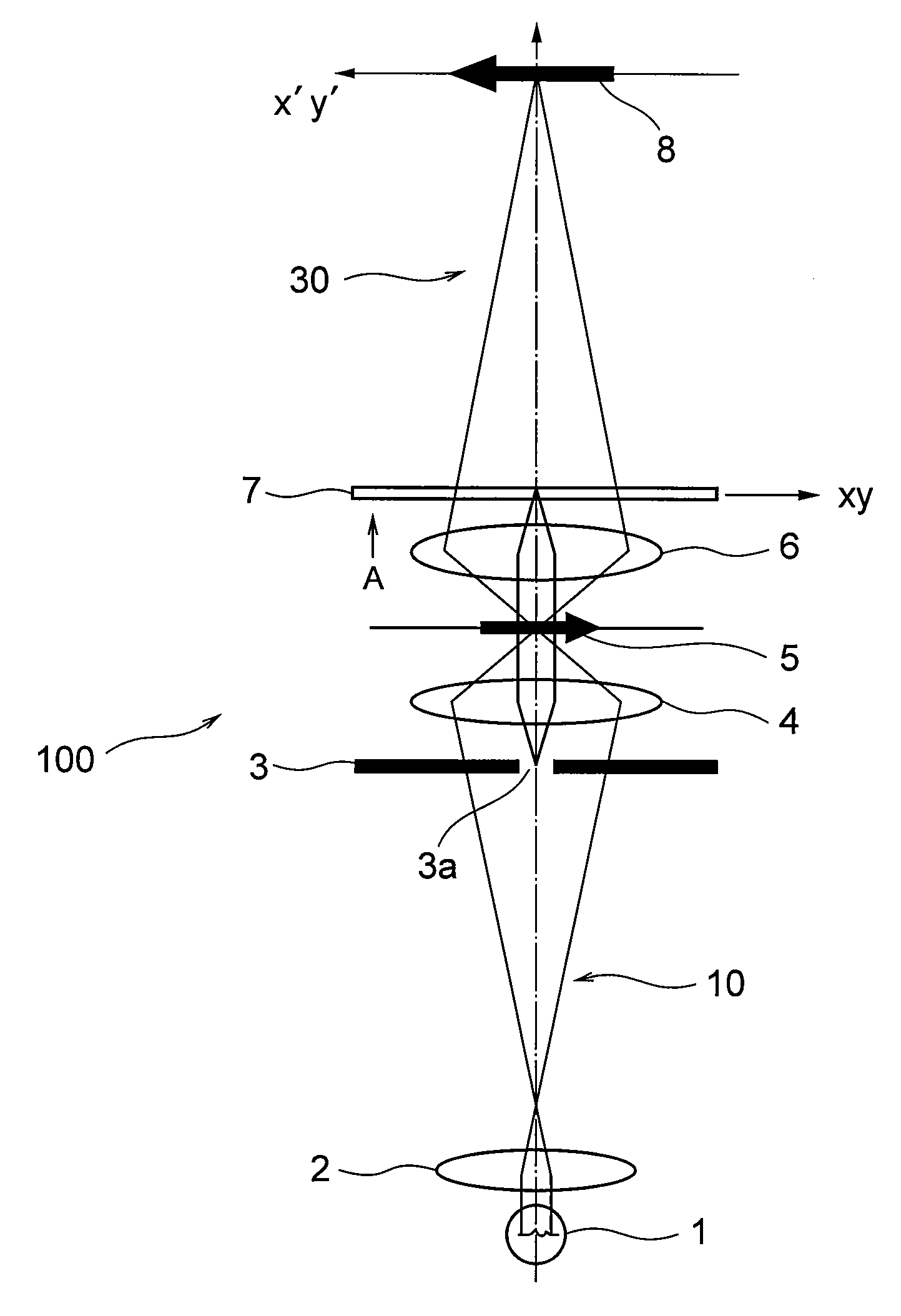
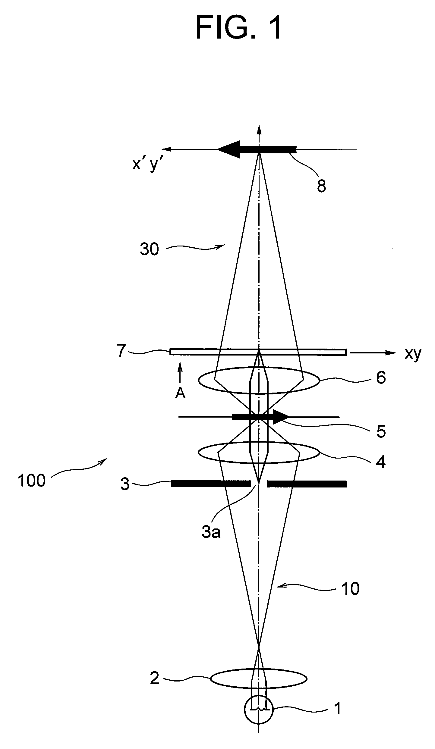
[0033]FIG. 1 is schematic diagram showing a microscope apparatus according to a first embodiment of the present invention.

[0034]In FIG. 1, illumination light emitted from a white light source 1 such as a halogen lamp or a mercury lamp is converged by a collector lens 2, transmitted through a slit member 3 having a slit aperture 3a, and illuminates a sample 5 by an illumination optical system 10 including a condenser lens 4. Light transmitted through the sample 5 is converged by an objective lens 6, transmitted through a π phase plate 7 giving a phase difference of 180 degrees, and forms a sample image on an image plane 8 through an imaging optical system 30.

[0035]The π phase plate 7 is disposed in the vicinity of a rear focal plane of the objective lens 6, and the slit member 3 is disposed in the vicinity of a front focal plane of the condenser lens 4, which is a conjugate plane with the π phase plate 7. Here, the rear focal plane of the objective lens 6 and the front focal plane of...

second embodiment

[0061]Then, a microscope apparatus according to a second embodiment of the present invention is explained with reference to FIGS. 7A, 7B, 7C, and 8A through 8F. The microscope apparatus 100 according to the second embodiment has the same configuration of the optical system of the microscope apparatus 100 according to the first embodiment, and the only difference is that a portion of the π phase plate has a filter, which controls transmittance, so that the explanation of the over all configuration is the same as that of the first embodiment. Accordingly, duplicated explanations are omitted.

[0062]FIGS. 7A, 7B and 7C are diagrams showing a π phase plate 17 with a filter having transmittance t disposed in a microscope apparatus 100 according to a second embodiment, in which FIG. 7A shows construction of the π phase plate 17, FIG. 7B shows transmittance characteristics of the π phase plate 17, and FIG. 7C shows phase characteristics of the π phase plate 17.

[0063]In FIG. 7A, an outer circ...

third embodiment

[0069]Then, a microscope apparatus according to a third embodiment of the present invention is explained. Since the third embodiment differs construction of a slit member and a phase plate thereof from that of the first embodiment, and the other constructions are the same as the first embodiment, so that only the phase plate and the aperture member are explained.

[0070]FIG. 9A is a diagram showing a π phase plate 27 disposed in a microscope apparatus according to the third embodiment, showing construction and positional relation of an annular aperture 23a formed on an aperture portion 3. In other words, in the third embodiment, an aperture member 3 with an annular aperture 23a having a width of d2 is disposed at the position where the slit member 3 is disposed in the FIG. 1, and a π phase plate 27 having a phase plate 27e introducing phase difference of −π / 2 with a disc shape, and, in the outer circle side thereof, a phase plate 27f introducing phase difference of +π / 2 with a disc sh...


PUM


Abstract

Providing a microscope apparatus capable of observing phase variation of a phase object with sufficient contrast with a white light source having an area such as a halogen lamp and a mercury lamp commonly used in a microscope. A microscope apparatus 100 comprising: an illumination optical system 10 that illuminates a sample 5 with illumination light emitted from a light source 1; an imaging optical system 30 that converges light emitted from the sample to form a sample image by an objective lens 6; an aperture member 3 that is disposed in the illumination optical system in the vicinity of a conjugate plane of a rear focal plane of the objective lens and has an aperture for limiting the illumination light; and a filter member that includes a phase plate 7 that is disposed in the imaging optical system in the vicinity of the rear focal plane of the objective lens or in the vicinity of the conjugate plane of the rear focal plane of the objective lens and has a first phase area introducing phase difference of 180 degrees into the light from the sample and a second phase area; a phase boundary portion between the first phase area and the second phase area being disposed in a conjugate aperture of the aperture.

Description

TECHNICAL FIELD[0001]The present invention relates to a microscope apparatus.BACKGROUND ART[0002]An object to be observed by a microscope is mainly divided into two categories, in which one is an amplitude object and the other is a phase object. Since the amplitude object varies brightness or colors thereof, the variation can be detected as a contrast by an eye or an imaging device such as a CCD. On the other hand, since a phase object only varies phase of light, it shows a poor contrast and hardly distinguishable as it is. Accordingly, there has been proposed various methods for changing phase variation of a phase object into discernible variation in contrast such as Japanese Patent Application Laid-Open No. 11-95174.[0003]However, in examples disclosed in Japanese Patent Application Laid-Open No. 11-95174, in order to make phase variation of a phase object discernible variation in contrast, a light source is limited to a coherent light source.DISCLOSURE OF THE INVENTION[0004]The p...

Claims


Application Information

Patent Timeline
IPC IPC(8): G02B21/00
CPCG02B21/14
Inventor MATSUI, KUMIKO
Owner NIKON CORP
Why Eureka
Try Eureka