Method for producing fuel cell electrolyte membrane and method for producing membrane-electrode assembly

a fuel cell electrolyte and electrolyte technology, applied in the direction of final product manufacturing, sustainable manufacturing/processing, electrochemical generators, etc., can solve the problems of reducing the power generation efficiency of the membrane-electrode assembly, the electrolyte membrane is likely to be damaged, etc., to achieve the effect of reducing the interface resistance between the electrolyte membrane surface and the electrode catalyst layer, increasing the effective contact area between the electrolyte membrane surface and the electrode catalys

Active Publication Date: 2009-07-09
TOYOTA JIDOSHA KK
View PDF11 Cites 12 Cited by
  • Summary
  • Abstract
  • Description
  • Claims
  • Application Information

AI Technical Summary

Benefits of technology

[0025]According to the present invention, an electrolyte membrane has recesses and projections on the surface thereof such that the effective contact area between the electrolyte membrane surface and an electrode catalyst layer can be increased. Further

Problems solved by technology

However, an electrolyte membrane is likely to be damaged when an electrode catalyst layer on which recesses and projections have been formed is pressure-welded to an electrolyte membrane having a flat face.
In addition, the p

Method used


Image

  • Method for producing fuel cell electrolyte membrane and method for producing membrane-electrode assembly
  • Method for producing fuel cell electrolyte membrane and method for producing membrane-electrode assembly
  • Method for producing fuel cell electrolyte membrane and method for producing membrane-electrode assembly

Examples


Embodiment Construction

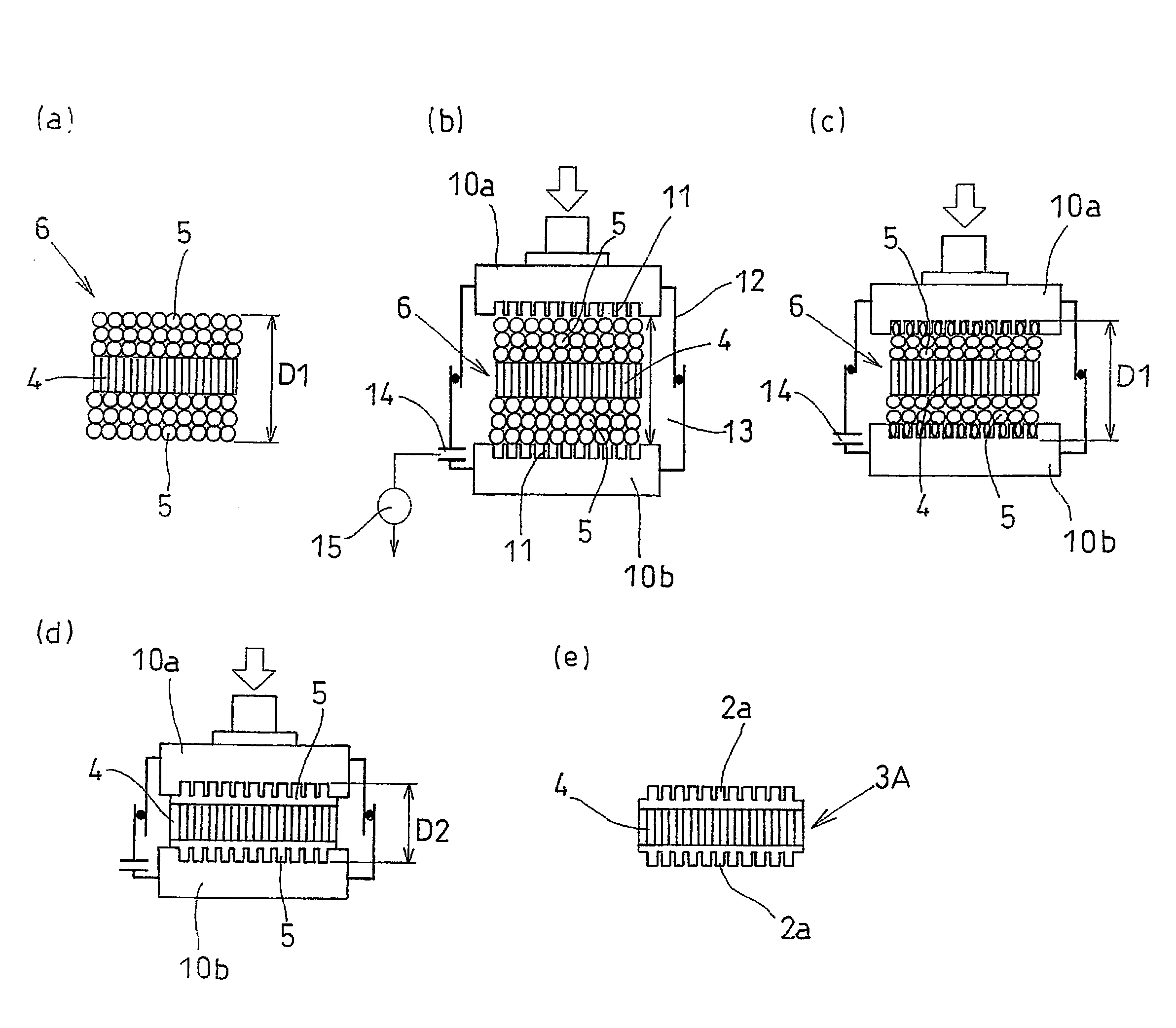
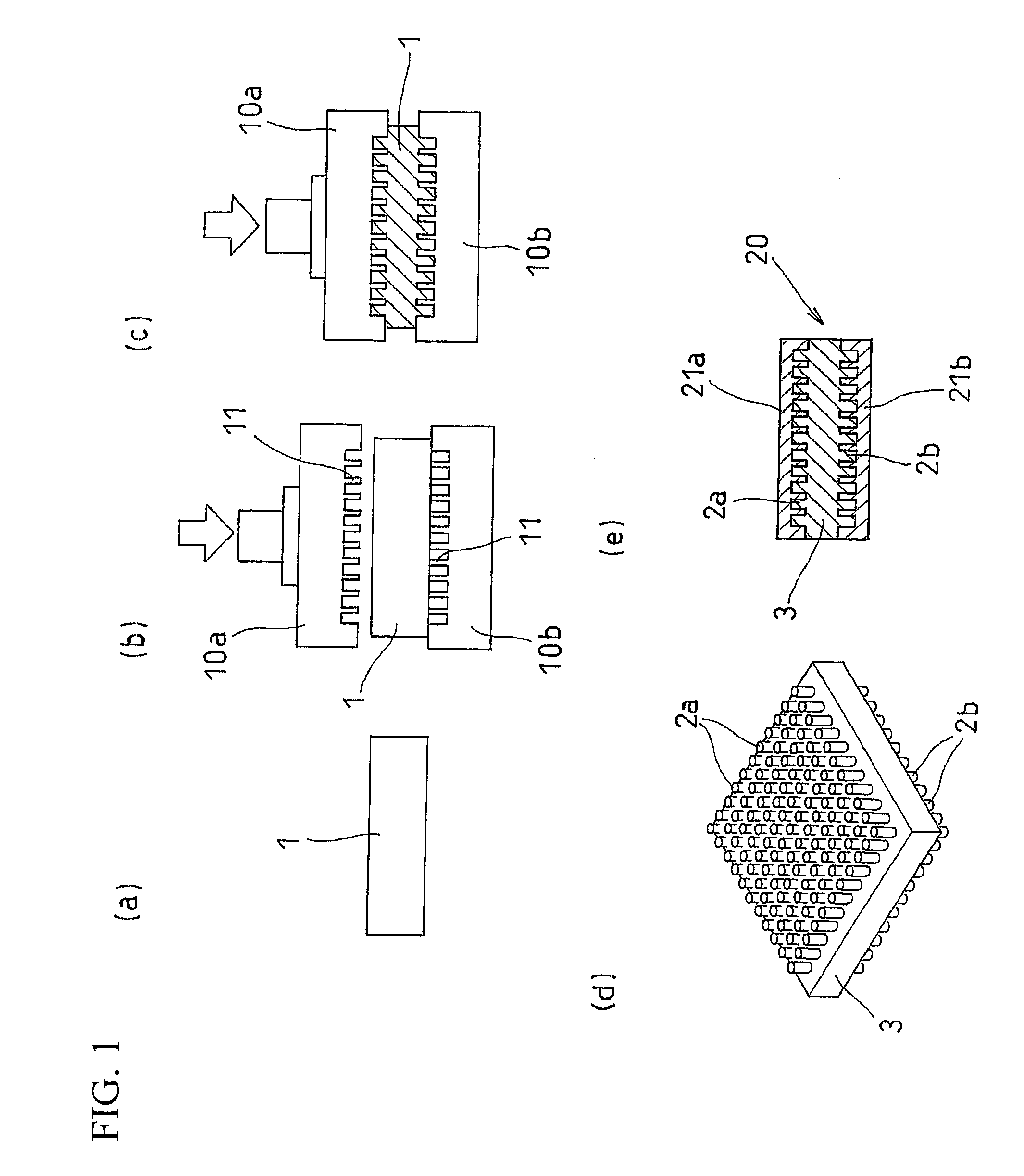
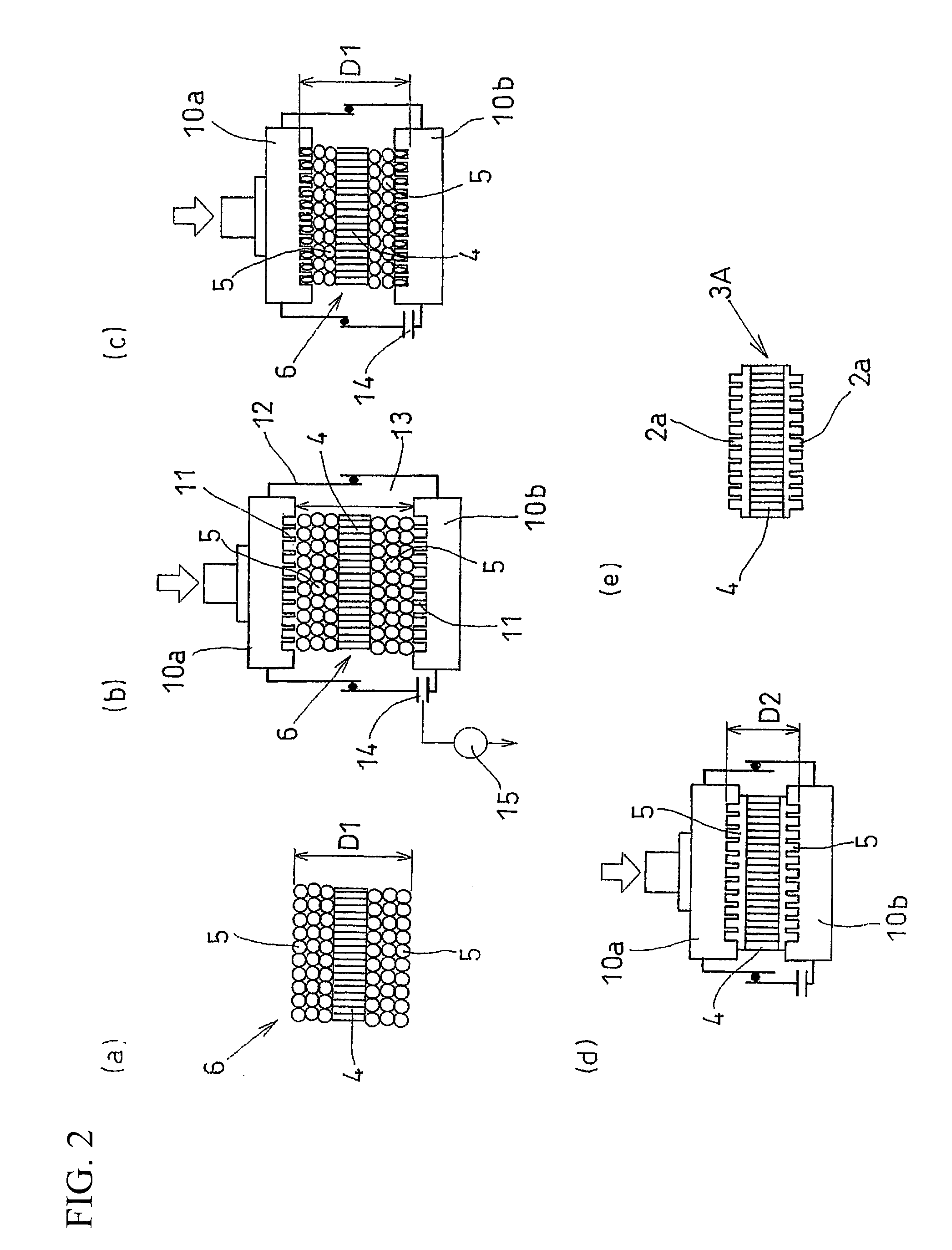
[0031]Hereinafter, the present invention is described based on the embodiments thereof with reference to the drawings. FIGS. 1 and 2 show explanatory diagrams of the method for producing a fuel cell electrolyte membrane of the present invention. FIG. 3 is an explanatory diagram of one embodiment of the production of the membrane-electrode assembly of the present invention with the use of a prepared fuel cell electrolyte membrane.

[0032]In the embodiment shown in FIG. 1, a fluorine-based electrolyte membrane 1 (thickness: approximately 25 μm to 70 μm) is used as a starting material (FIG. 1a). The electrolyte membrane 1 is positioned between upper and lower heating plates 10a and 10b each having recesses and projections 11 on the surface thereof (FIG. 1b). The electrolyte membrane 1 is heated and pressed by lowering the heating plate 10a (FIG. 1c). The temperatures of heating plates 10a and 10b are preferably approximately 170° C. to 300° C.

[0033]The depth of a recess (or the height of...


PUM

PropertyMeasurementUnit
Pressureaaaaaaaaaa
Areaaaaaaaaaaa
Ion exchange propertiesaaaaaaaaaa

Abstract

According to the present invention, an electrolyte membrane having recesses and projections on the surface thereof is obtained. In addition, a membrane-electrode assembly comprising the electrolyte membrane, in which the effective contact area between the electrolyte membrane surface and an electrode catalyst layer is increased, is obtained. An electrolyte membrane 1 which comprises a fluorine-based electrolyte is heated and pressed with the use of plates 10a and 10b each having recesses and projections 11 on the surface thereof such that recesses and projections 2a and 2b are formed on the surface of the electrolyte membrane 1. Thereafter, the electrolyte membrane 1 is subjected to a treatment for imparting ion exchange properties to an electrolyte polymer, such as hydrolysis, such that an electrolyte membrane 3 having recesses and projections on the surface thereof is obtained. Electrode catalyst layers 21a and 21b are separately laminated on the both surfaces of the electrolyte membrane 3 such that a membrane-electrode assembly 20 is obtained.

Description

TECHNICAL FIELD[0001]The present invention relates to a method for producing a fuel cell electrolyte membrane and a method for producing membrane-electrode assembly using the produced electrolyte membrane.BACKGROUND ART[0002]A polymer electrolyte fuel cell has been known as one type of fuel cell. Since a polymer electrolyte fuel cell is characterized by low operating temperatures (up to approximately 80° C. to 100° C.), low cost, and its compact size when compared with different types of fuel cells, it is expected to serve as an automobile power source and the like.[0003]As shown in FIG. 4, in a polymer electrolyte fuel cell, a membrane-electrode assembly (MEA) 50, which is used as a main component, is sandwiched by separators 51 each having a fuel (hydrogen) gas channel and an air gas channel such that a single fuel cell 55, referred to as a single cell, is formed. A membrane-electrode assembly 50 has a structure in which an anode-side electrode catalyst layer 53a is laminated on o...

Claims


Application Information

Patent Timeline
IPC IPC(8): B05D5/12H01M8/10B32B37/00
CPCH01M8/0291H01M8/1006H01M8/1023H01M8/1039Y10T156/1089Y02E60/521Y10T156/109Y10T156/1039H01M8/1093H01M8/0289Y02P70/50Y02E60/50
Inventor SUZUKI, HIROSHI
Owner TOYOTA JIDOSHA KK
Why Eureka
Try Eureka