Inductive power supply with duty cycle control

Active Publication Date: 2009-07-09
PHILIPS IP VENTURES BV
View PDF52 Cites 481 Cited by
  • Summary
  • Abstract
  • Description
  • Claims
  • Application Information

AI Technical Summary

Benefits of technology

[0009]The present invention provides a simple and effective system and method for providing a selected amount of wireless power while maintaining a high transfer efficiency. Adjustment of duty cycle provides another level of control of wireless power transfer, one which

Problems solved by technology

In these systems, maintaining an acceptable power transfer efficiency can be difficult.
One issue with these systems is that the power transfer efficiency between the inductive power supply and the remote device is a function of how close the operating frequency is to resonance.
So, while adjusting the operating frequency or resonant frequency can provi

Method used


Image

  • Inductive power supply with duty cycle control
  • Inductive power supply with duty cycle control
  • Inductive power supply with duty cycle control

Examples


Example

I. Overview

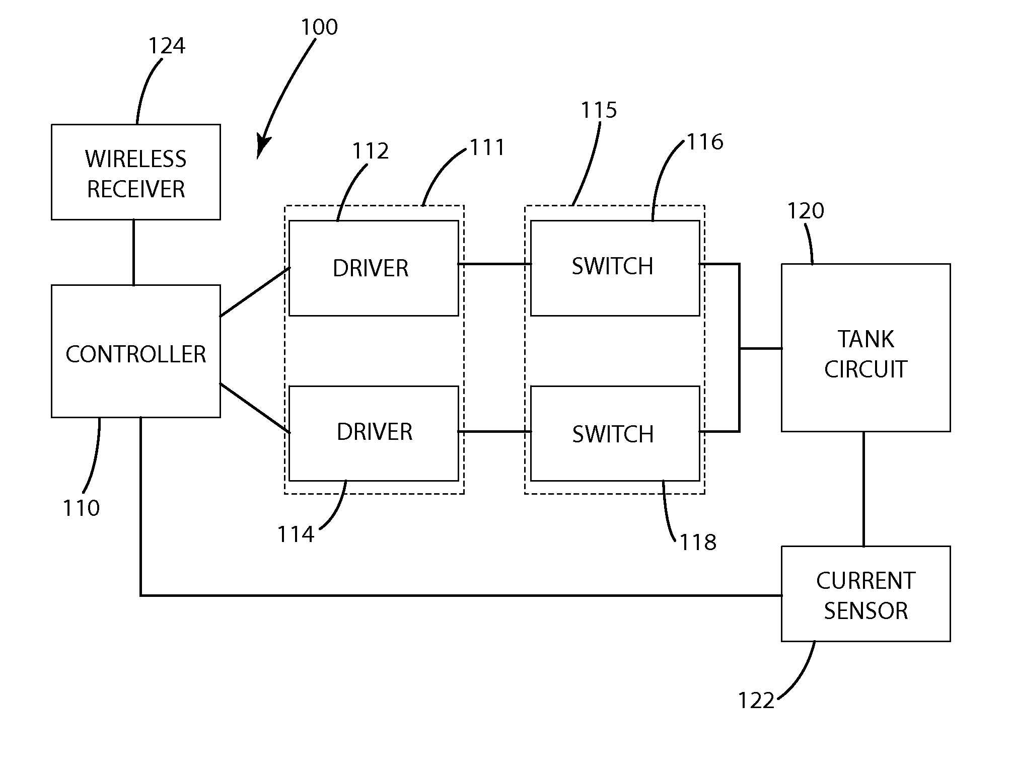
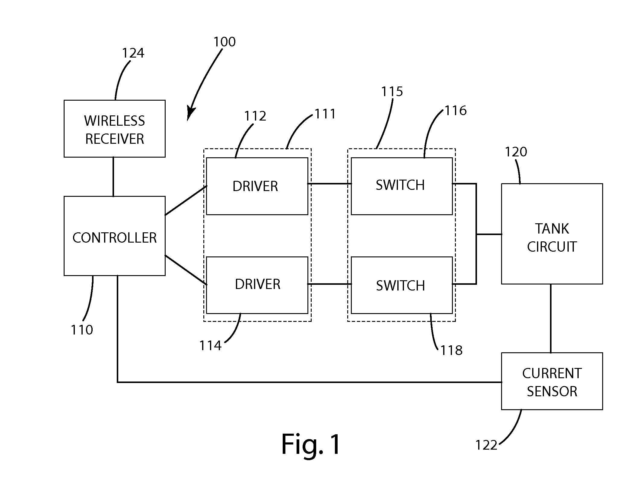
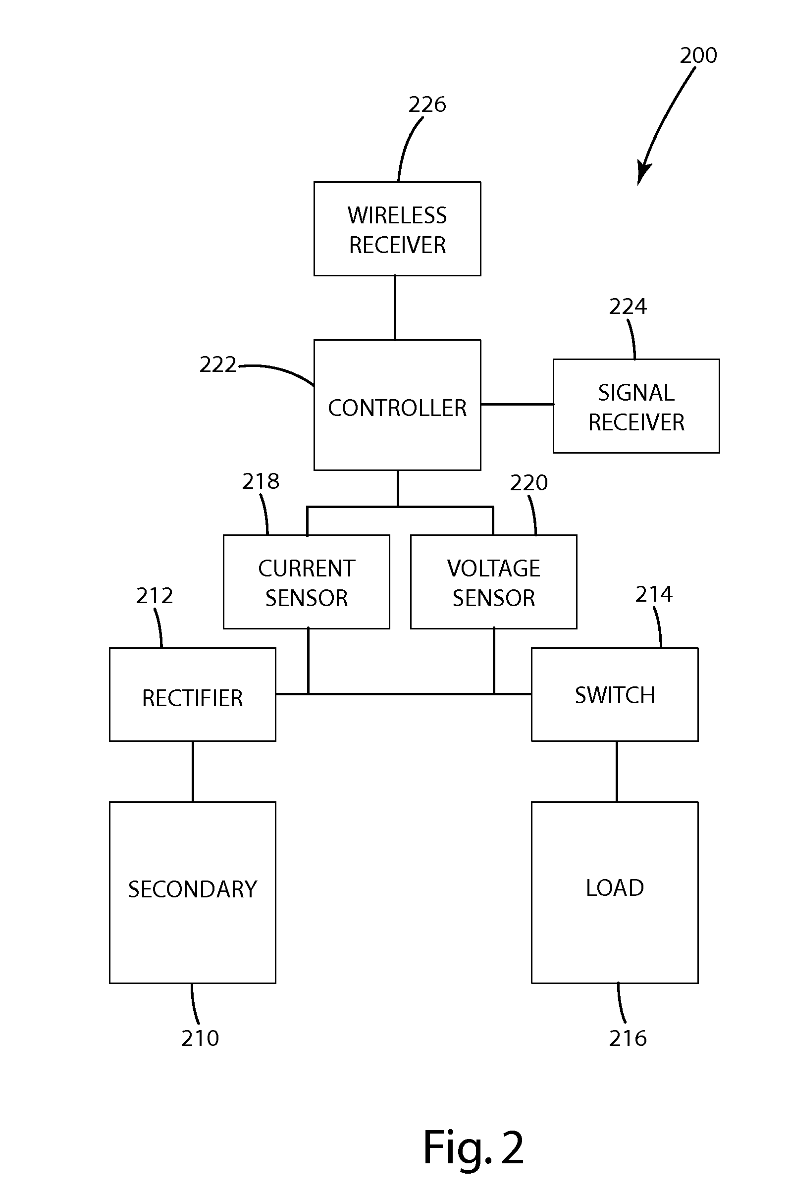
[0019]An inductive power supply or primary circuit in accordance with an embodiment of the present invention is shown in FIG. 1, and generally designated 100. The primary circuit 100 includes a primary controller 110, a driver circuit 111 including a pair of drivers 112, 114, a switching circuit 115 including a pair of switches 116, 118, a tank circuit 120 a primary sensor 122 and an optional wireless receiver 124. The primary controller 110, driver circuit 111 and the switching circuit 115 together generate an AC signal at a selected frequency and selected duty cycle that is applied to the tank circuit 120 to create an inductive field for transferring power wirelessly to a secondary circuit. A secondary circuit in accordance with an embodiment of the present invention is shown in FIG. 2, and generally designated 200. The secondary circuit 200 may include a secondary 210, a rectifier 212, a switch 214, a load 216, a current sensor 218 or voltage sensor 220, a secondary co...


PUM


Abstract

An inductive power supply that maintains resonance and adjusts duty cycle based on feedback from a secondary circuit. A controller, driver circuit and switching circuit cooperate to generate an AC signal at a selected operating frequency and duty cycle. The AC signal is applied to the tank circuit to create an inductive field for powering the secondary. The secondary communicates feedback about the received power back to the primary controller. The power transfer efficiency may be optimized by maintaining the operating frequency substantially at resonance, and the amount of power transferred may be controlled by adjusting the duty cycle.

Description

[0001]This application claims the benefit of U.S. Provisional Application No. 61 / 019,411, filed on Jan. 7, 2008.[0002]The present invention relates to inductive power and more particularly to a system and method for wirelessly supplying power.BACKGROUND OF THE INVENTION[0003]In recent years, wireless power supply systems have received increased attention because of some of their benefits over traditional wired power supply systems. Some more basic wireless power supply systems are specifically designed to charge a particular device, which can help minimize power transfer efficiency issues. Other wireless power supply systems attempt to account for misalignment, charge different remote devices and provide different amounts of power. In these systems, maintaining an acceptable power transfer efficiency can be difficult.[0004]Some wireless power systems adjust the operating frequency of an AC signal across the tank circuit closer to or further from resonance to increase or decrease the...

Claims


Application Information

Patent Timeline
IPC IPC(8): H02J17/00H02J7/00
CPCH02J5/005H02M3/33523H02J7/025H02J50/90H02J50/80H02J50/12H02J7/00034Y02B70/10H02J50/402H02J50/10H02J50/40H04B5/0093H04B5/0037
Inventor BAARMAN, DAVID W.MOLLEMA, SCOTT A.SCHWANNECKE, JOSHUA K.LEPPIEN, THOMAS JAYBURNS, KENNETH MICHAEL
Owner PHILIPS IP VENTURES BV
Why Eureka
Try Eureka