Substrate processing apparatus and substrate transferring method

a substrate processing and substrate technology, applied in the direction of instruments, charge manipulation, furnaces, etc., can solve the problems of shortening the processing time, affecting the transfer efficiency of substrates, and a relatively long time to transfer wafers, etc., to achieve the effect of high transfer efficiency

Active Publication Date: 2007-11-20
TOKYO ELECTRON LTD
View PDF7 Cites 22 Cited by
  • Summary
  • Abstract
  • Description
  • Claims
  • Application Information

AI Technical Summary

Benefits of technology

[0013]The present invention is contrived on the basis of such a situation. It is, therefore, a primary object of the present invention to provide a substrate processing apparatus capable of transferring a substrate with high transfer efficiency, even in case where a processing time is shorter than a transfer time.

Problems solved by technology

However, if the robot is rotated by 180° whenever a wafer is loaded in one processing chamber, it takes a relatively long time to transfer the wafer.
However, when comparing the time required for performing a process in each processing chamber of the cluster tools with that for transferring an unprocessed wafer from a load-lock chamber to the processing chamber, there are cases that the processing time is shorter than the transfer time and vice versa.
However, in case where the processing time is shorter than the transfer time, the processing on the wafer must already have been completed in the processing chamber while the unprocessed wafer being transferred from the load-lock chamber by the substrate transfer device.
Thus, the configuration of the aforementioned prior art does not help to facilitate the transfer of the wafer effectively since there is no case where the unprocessed wafer stands by until performing a process on a prior wafer is completed in the processing chamber, in such a state where a wafer is supported by the substrate transfer device in the transfer chamber.
Further, there are the following problems in an apparatus for performing a vacuum process of a cluster tools or the like.
As a result, there is a concern for contaminating the wafer.
However, the aforementioned method is not effective since shock waves are generated when opening the valve in the case of employing a connecting line between the vacuum chambers.
However, it is difficult to respond to such needs with the conventional technology.

Method used


Image

  • Substrate processing apparatus and substrate transferring method
  • Substrate processing apparatus and substrate transferring method
  • Substrate processing apparatus and substrate transferring method

Examples


Embodiment Construction

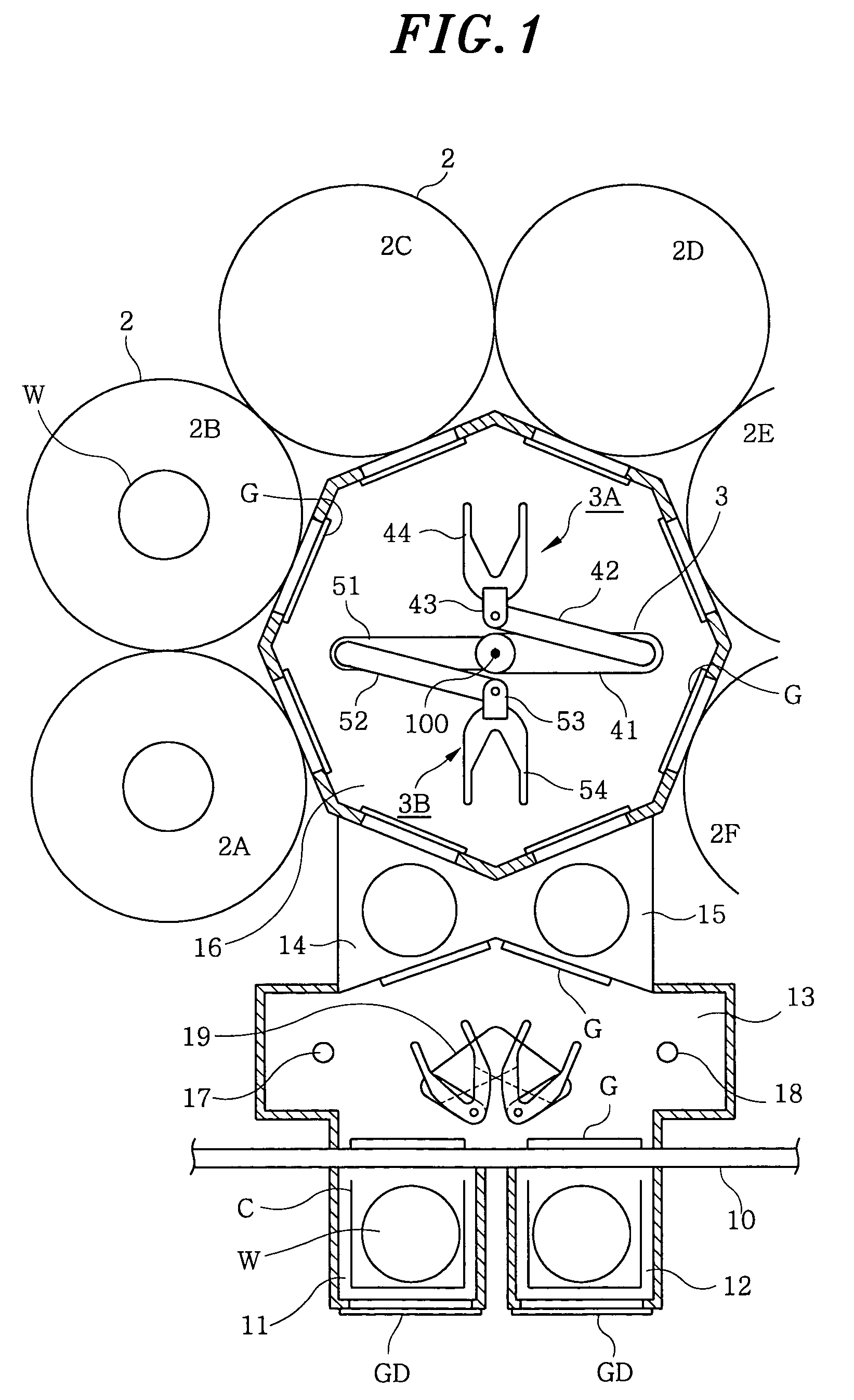
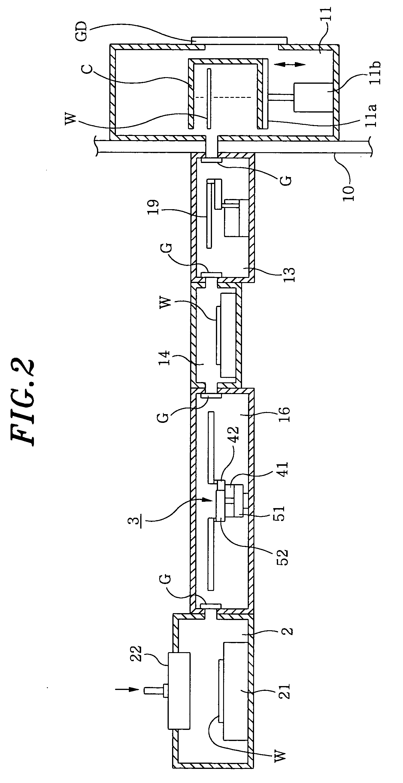
[0046]FIGS. 1 and 2 are views for showing a preferred embodiment of a substrate processing apparatus in accordance with the present invention. The substrate processing apparatus includes, e.g., two cassette chambers 11 and 12 each having an airtight structure, in which a cassette (transfer container) C accommodating a plurality of wafers, i.e., substrates, is loaded. Each gate door GD is prepared at the atmosphere side of each of the cassette chambers 11 and 12 to thereby airtightly shut off the corresponding cassette chamber from the atmosphere. As shown in FIG. 2, an elevator 11b is installed in each of the cassette chambers 11 and 12 so as to elevate a cassette mounting table 11a and dispose a wafer supporting groove in the cassette C at an excess level of a first transfer device that will be discussed later, subsequently.

[0047]Inner sides of the cassette chambers 11 and 12 are airtightly connected to a first transfer chamber 13 having an airtight structure. And, the first transf...


PUM

PropertyMeasurementUnit
pressureaaaaaaaaaa
pressureaaaaaaaaaa
processing timeaaaaaaaaaa

Abstract

Shock waves occurring when opening a gate valve between two vacuum chambers and peeling of particles by a viscous force taking place when a gas is supplied into a vacuum chamber are necessary to be suppressed by the apparatus and method of the invention, whereby contamination of a substrate by particles is suppressed. If one vacuum chamber is a substrate processing chamber for performing a vacuum process on the substrate and the other chamber is a transfer chamber having a substrate transfer device therein, the gate valve is opened when inner pressures of both the vacuum chambers are less than 66.5 Pa and higher one thereof is less than twice a lower one thereof. Preferably, a purge gas for peeling of particles is supplied, before supplying the purge gas for pressure control, into the substrate processing chamber with a flow rate greater than that of the purge gas for pressure control.

Description

FIELD OF THE INVENTION[0001]The present invention relates to a substrate processing apparatus in which a plurality of substrate processing chambers are airtightly coupled to a transfer chamber having a substrate transfer device for transferring a substrate, e.g., semiconductor wafer (hereinafter, referred to as ‘wafer’), and a method for transferring a substrate thereto; and, more particularly, to a technology for transferring a substrate between two vacuum chambers in a substrate processing apparatus having a first and a second vacuum chamber coupled to each other through a sluice valve and performing a vacuum process on the substrate.BACKGROUND OF THE INVENTION[0002]In a semiconductor fabrication apparatus, there is a known mechanism such that a plurality of processing chambers is coupled to a transfer chamber having a substrate transfer device, i.e., cluster tools or multi-chamber mechanism. Such a mechanism has some merits that a vacuum processing on a substrate can be performed...

Claims


Application Information

Patent Timeline
Patent Type & Authority Patents(United States)
IPC IPC(8): G06F19/00G06F7/66B65G49/00H01L21/00H01L21/02H01L21/3065H01L21/677
CPCH01L21/67276H01L21/67745H01L21/67742
Inventor TEZUKA, KAZUYUKIKOIZUMI, HIROSHIMORIYA, TSUYOSHINAKAYAMA, HIROYUKI
Owner TOKYO ELECTRON LTD
Why Eureka
Try Eureka