Adaptive Milking System

a technology for milking systems and mammals, applied in milking devices, dairy products, catheters, etc., can solve problems such as damage to the teat ends of cows, dairyman milkers often getting distracted, and no longer possible to have a single letdown delay, so as to improve the operation

Inactive Publication Date: 2009-08-13
TECH HLDG
View PDF12 Cites 5 Cited by
  • Summary
  • Abstract
  • Description
  • Claims
  • Application Information

AI Technical Summary

Problems solved by technology

Because of this, it is no longer possible to have a single letdown delay 78 that is appropriate for all of the cows in a herd.
Unfortunately, dairyman milkers often get distracted after they have started the manual mode, and the milking unit teatcups stay attached long after the cow stops giving milk.
This overmilking can cause damage to the teat ends of the cows.
This limits the total amount of time that a cow can be in manual mode, and also prevents a milking unit from being left on a cow that is not producing milk.

Method used


Image

  • Adaptive Milking System
  • Adaptive Milking System
  • Adaptive Milking System

Examples


Embodiment Construction

Prior Art

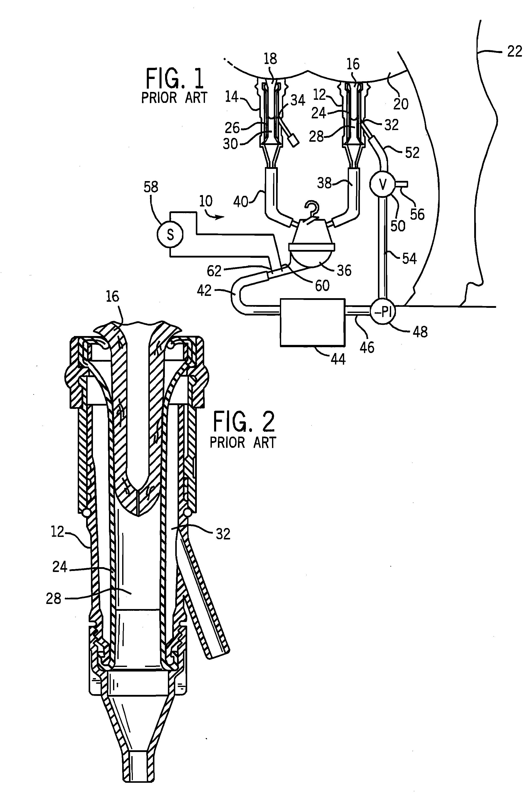
[0013]FIG. 1 shows a milking system 10 having a plurality of teatcups such as 12, 14 connected to respective teats such as 16, 18 depending from the udder 20 of a mammal 22 such as a cow. Each teatcup has a liner or inflation such as 24, 26 around a respective teat, and defining a milk flow passage such as 28, 30 within the liner below the teat, and a pulsation chamber such as 32, 34 outside the liner between the liner and the teatcup shell. The teatcup and liner are shown and described in U.S. Pat. No. 4,530,307, incorporated herein by reference. A milking claw 36, for example as shown in U.S. Pat. No. 4,537,152, incorporated herein by reference, has a plurality of inlets receiving milk through tubes such as 38, 40 connected to respective teatcups to receive milk from respective milk flow passages such as 28, 30. The claw has a discharge tube 42 connected to milk collection container 44 having a vacuum connection tube 46 connected to a source of negative pressure 48. There...


PUM


Abstract

A method for milking a mammal is provided by interactively and variably responding to sensed and monitored milk flow and adaptively varying one or more given milking parameters in response thereto for the individual mammal.

Description

BACKGROUND AND SUMMARY[0001]The invention relates to systems for milking mammals, including cows.[0002]Known methods for milking mammals include attaching teatcups to the teats of the mammal for milk flow to a claw and collection container, sensing of the milk flow, comparing the sensed milk flow to a given threshold, and detaching the teatcups from the teats upon reaching such given threshold, e.g. after a given delay enabling full milk flow to be established, the teatcups are detached when the milk flow drops below a given threshold.[0003]The present invention arose during continuing development efforts directed toward improving operation of the noted systems.BRIEF DESCRIPTION OF THE DRAWINGS[0004]FIGS. 1-3 are taken from U.S. Pat. No. 5,218,924, incorporated herein by reference.[0005]FIG. 1 schematically illustrates a milking system known in the prior art.[0006]FIG. 2 shows a teatcup and liner during the on portion of a pulsation milking cycle as known in the prior art.[0007]FIG....

Claims


Application Information

Patent Timeline
Patent Type & Authority Applications(United States)
IPC IPC(8): A01J5/007
CPCA01J5/017A01J5/007
Inventor TUCKER, GEORGE H.ERDMAN, ROGER K.
Owner TECH HLDG
Why Eureka
Try Eureka