Method for determining pump flow rate

a technology of flow rate and pump, applied in the field of pumping stations, can solve the problems of undetectable cost of sensors, reduced flow rate (f), and prone to variation in inflow (i)

Active Publication Date: 2009-08-13
MULTITRODE
View PDF9 Cites 10 Cited by
  • Summary
  • Abstract
  • Description
  • Claims
  • Application Information

AI Technical Summary

Benefits of technology

[0016]The operating condition may be that the flow rate indicator is less than a predetermined flow rate threshold. The predetermined flow rate threshold may be calculated as a percentage reduction of a prior flow rate indicator.
[0017]The...

Problems solved by technology

The instantaneous flow rate can be sensed using a flow meter, however, such sensors are undesirably expensive.
However, the inflow (I) may be prone to variation during a pump activation cycle.
In this event, t...

Method used


Image

  • Method for determining pump flow rate
  • Method for determining pump flow rate
  • Method for determining pump flow rate

Examples


Embodiment Construction

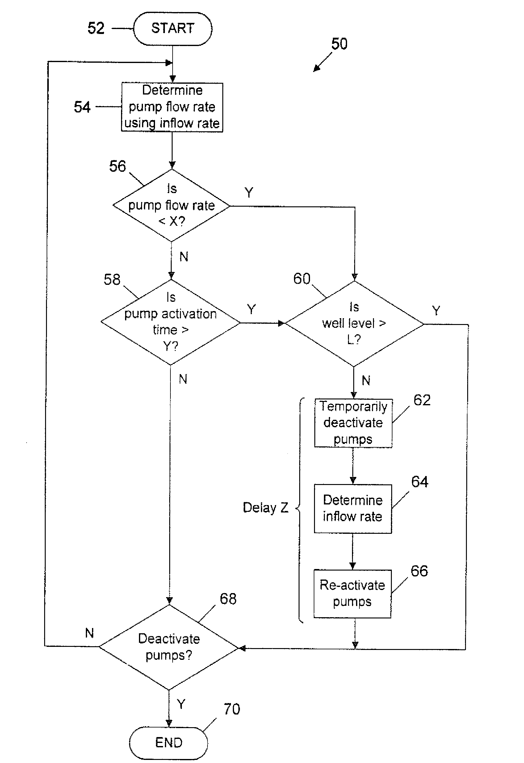
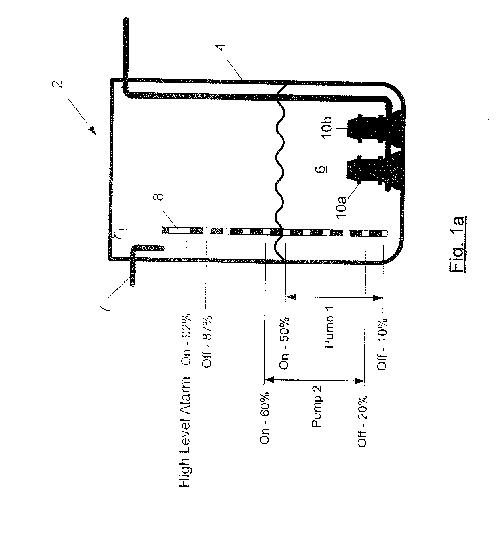
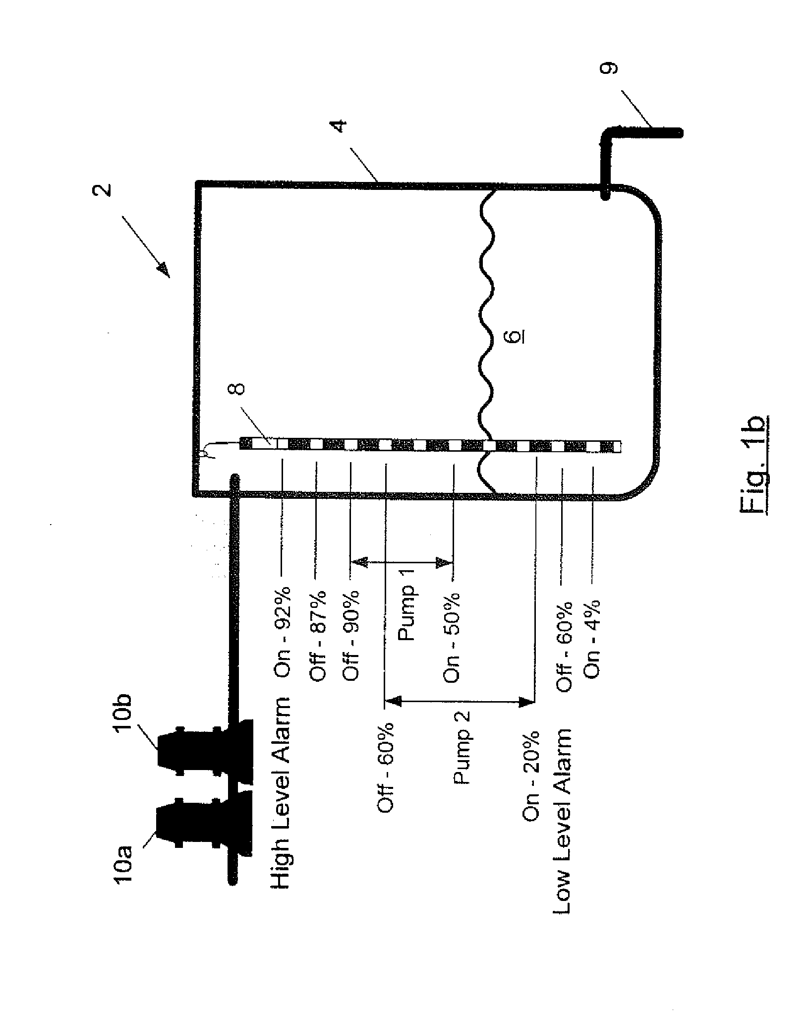
[0047]An embodiment of the present invention will now be described with reference to a controller 14 shown in FIG. 2 that is configured to control the pumping station 2 shown in FIG. 1a.

[0048]Referring initially to FIG. 1a, the pumping station 2 includes a level sensor 8 for sensing the liquid level in a well 4, and a pair of pumps 10a, 10b (e.g. three-phase variable speed drive pumps) for pumping liquid out of the well 4 to at least partially empty the well 4. Waste water including storm water flows into the well 4 through inlet 7. The controller 14 is suitable for controlling the activation and deactivation of the pumps 10 based on the sensed liquid level in the well 4. The activation and deactivation trigger points along the level sensor 8 for a first pump 10a and a second pump 10b are clearly shown in FIG. 1a. The controller 14 can also determine a well volume indicator (in the form of a variable or value), relating to the liquid volume in the well 4, using the liquid level sen...


PUM


Abstract

The present invention relates to a method for determining a flow rate indicator relating to the output flow rate of one or more activated pumps of a pumping station. The pumping station includes a well to be at least partially emptied by the pumps and an inlet through which inflow can be supplied into the well. The method includes the step of determining, using a computational device, an operating condition relating to the activated pumps. The pumps are temporarily deactivated and an inflow rate indicator relating to the inflow is determined using the computational device, responsive to the determination of the operating condition. The method further includes the step of determining, using the computational device, the flow rate indicator using the determined inflow rate indicator. The present invention is equally applicable to a well to be at least partially filled by the pumps.

Description

CROSS-REFERENCE TO RELATED APPLICATIONS[0001]This application is related to and claims priority from Australian Patent Application No.: 2008900591 filed on Feb. 8, 2008 and Australian Patent Application No.: 2008229735 filed on Oct. 1, 2008, each of which is incorporated by reference herein in its entirety.TECHNICAL FIELD[0002]The present invention generally relates to pumping stations. The present invention has particular, although not exclusive application to waste water pumping stations.BACKGROUND[0003]The reference to any prior art in this specification is not, and should not be taken as an acknowledgement or any form of suggestion that the prior art forms part of the common general knowledge.[0004]Pumping stations 2 for emptying sewage wells (FIG. 1a) and filling water wells (FIG. 1b) are known. As shown in FIG. 1a, waste water and sewage is supplied to the well 4 via an inlet 7 and the pumps 10 are configured to empty the well 4. In contrast, FIG. 1b shows that water drains fr...

Claims


Application Information

Patent Timeline
IPC IPC(8): F04B49/02G01F1/00
CPCG01F1/007G01F1/00F04D15/0218
Inventor DUNCAN, STUART MCMILLAN
Owner MULTITRODE
Why Eureka
Try Eureka