Eureka AIR delivers breakthrough ideas for toughest innovation challenges, trusted by R&D personnel around the world.

End effectors for a surgical cutting and stapling instrument

a technology of surgical stapling and end effectors, which is applied in the direction of surgical staples, paper/cardboard containers, manufacturing tools, etc., can solve the problems of increasing the time, complexity and overall cost causing the surgical stapling instrument to malfunction or be rendered inoperable, and the cost of designing and manufacturing multiple stapler sizes is greater than the cost of creating, so as to achieve the effect of increasing the time and complexity of laparoscopic surgical procedures

Active Publication Date: 2009-08-20
CILAG GMBH INT
View PDF99 Cites 1033 Cited by
  • Summary
  • Abstract
  • Description
  • Claims
  • Application Information

AI Technical Summary

Benefits of technology

The present disclosure provides improvements to a surgical stapling apparatus for sequentially applying a plurality of fasteners to body tissue and incising tissue. The improvements include a handle portion, an elongated body, and a disposable loading unit that can be attached to the elongated body. The disposable loading unit can be assembled to the elongated body in a way that prevents the detachment of the disposable loading unit from the elongated body, which can cause malfunctions or render the surgical stapling instrument inoperable. The surgical stapling instrument can also include a collar and a detent assembly for holding the disposable loading unit in place after it has been assembled to the elongated body. The instrument can also include a disposable loading unit with a staple cartridge, an anvil, and a sleeve that can hold the anvil in a closed position to apply a clamping force to soft tissue before staples are deployed. The surgical stapling instrument can also include a tongue that can engage the anvil to hold it in a closed position. The anvil can include a slot to receive a drive beam, and the drive beam can apply forces to the anvil to affect the deployment of staples into soft tissue. The anvil can also include a first member and a second member that can be deformed or press-fit together to support the first member. Overall, the improvements provide better stability and reliability of the surgical stapling apparatus.

Problems solved by technology

Such practices increase the time, complexity and overall costs associated with laparoscopic surgical procedures.
In addition, costs are greater in designing and manufacturing multiple stapler sizes, as opposed to creating a single, multipurpose stapler.
In previous surgical stapling devices, though, the disposable loading unit can become detached from the elongate body causing the surgical stapling instrument to malfunction or be rendered inoperable.
In various circumstances, a portion of the soft tissue can flow, or move, out of the distal end of the disposable loading unit and, as a result, the soft tissue may not be properly treated by the surgical stapling instrument.
In use, the drive beam can apply forces to the anvil which can cause the anvil to elastically and / or plastically deform and, as a result, affect the deployment of the surgical staples into the soft tissue.
Some disposable loading units having large anvils and / or staple cartridges may not fit, or easily fit, through the trocar.

Method used


Image

  • End effectors for a surgical cutting and stapling instrument
  • End effectors for a surgical cutting and stapling instrument
  • End effectors for a surgical cutting and stapling instrument

Examples


Embodiment Construction

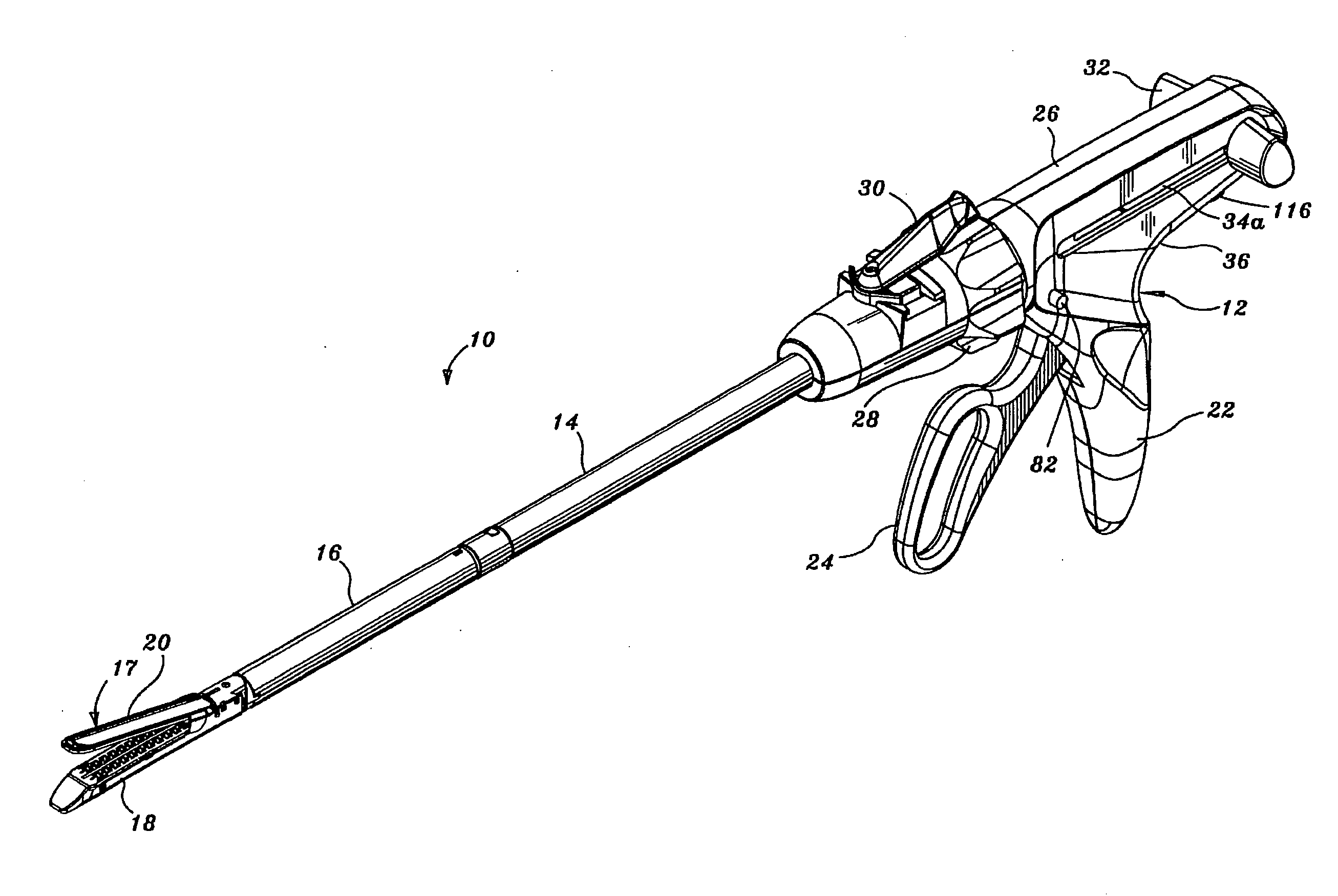
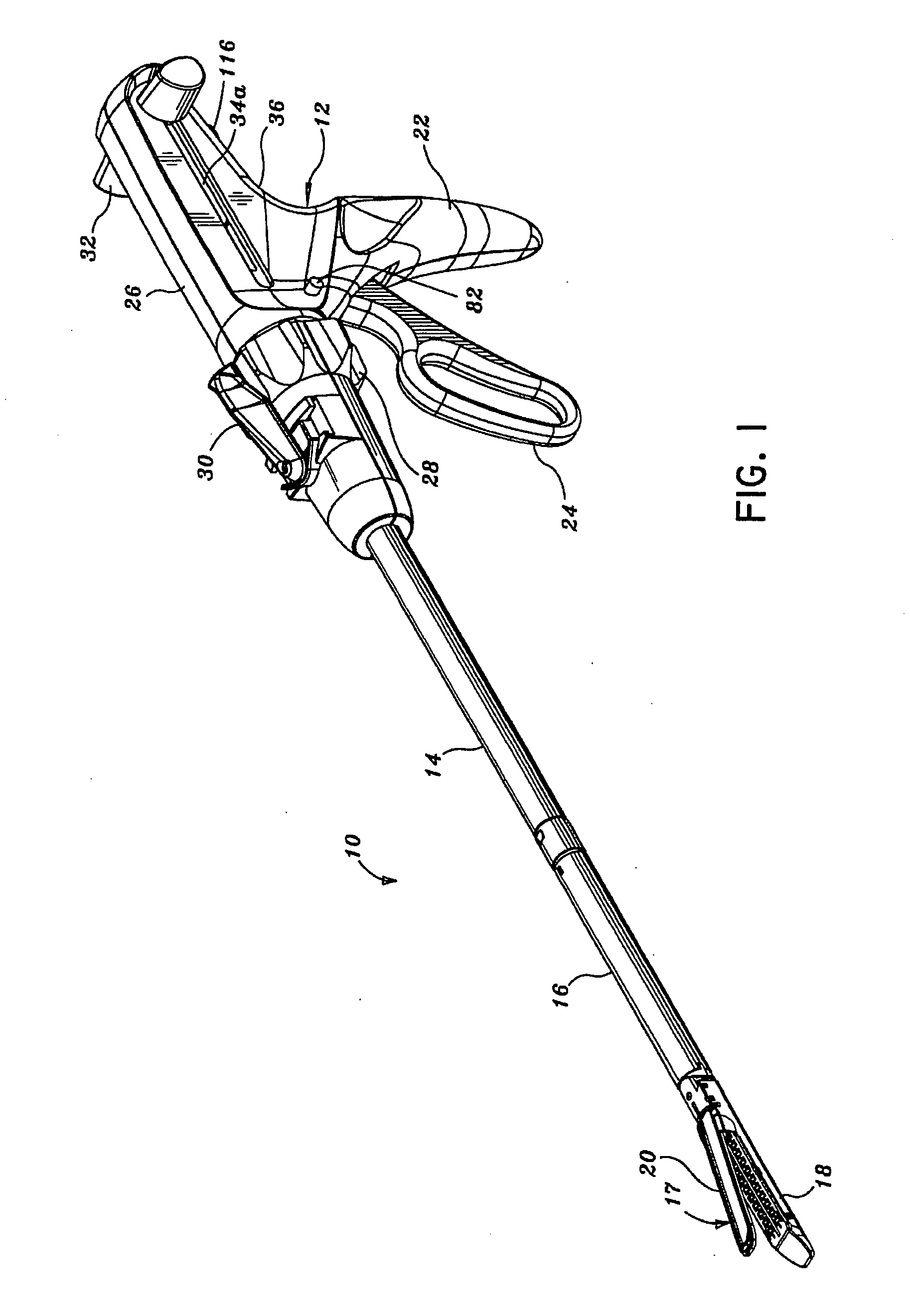
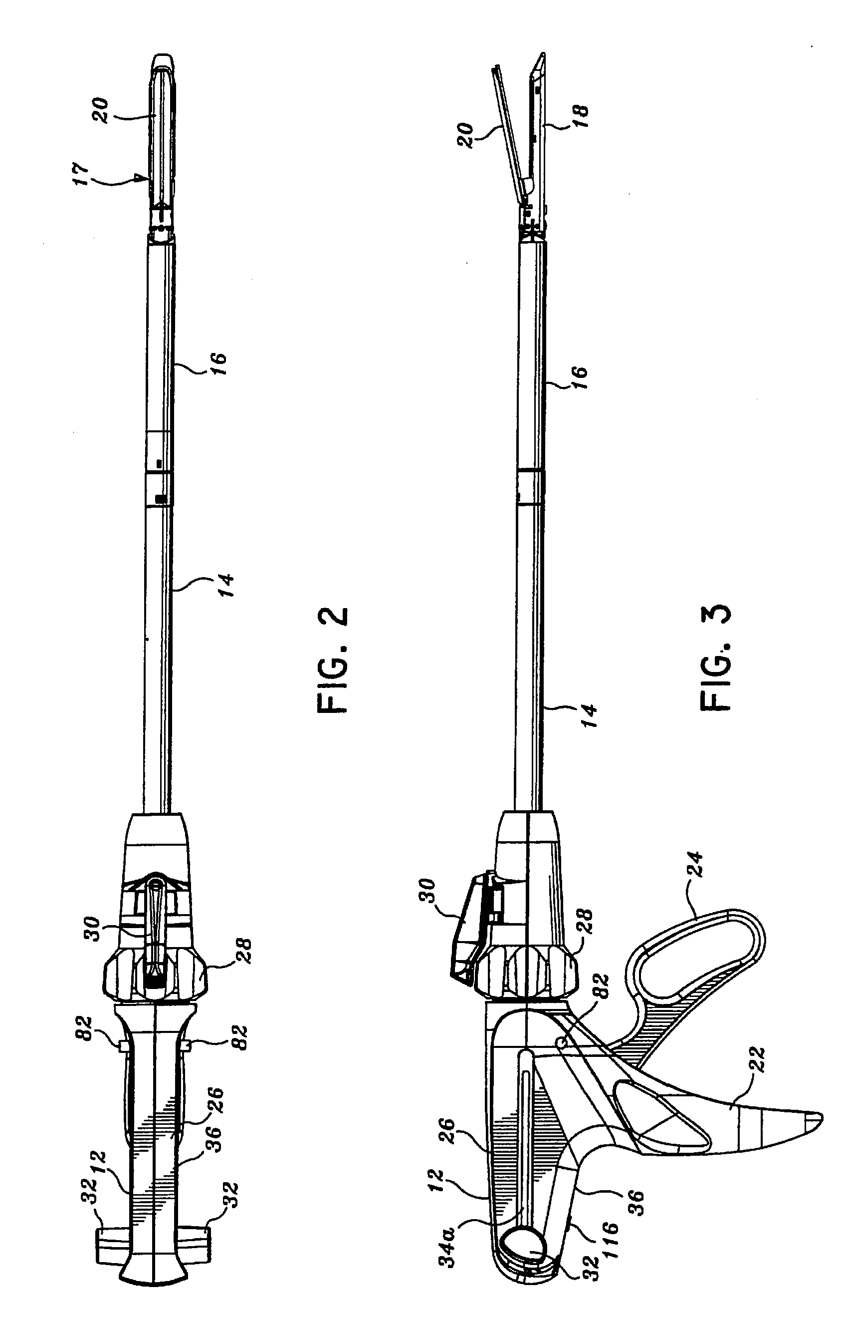
[0162]Preferred embodiments of the presently disclosed endoscopic surgical stapling apparatus will now be described in detail with reference to the drawings, in which like reference numerals designate identical or corresponding elements in each of the several views. Those of ordinary skill in the art will understand that the devices and methods specifically described herein and illustrated in the accompanying drawings are non-limiting exemplary embodiments and that the scope of the various embodiments of the present invention is defined solely by the claims. The features illustrated or described in connection with one exemplary embodiment may be combined with the features of other embodiments. Such modifications and variations are intended to be included within the scope of the present invention.

[0163]In the drawings and in the description that follows, the term “proximal”, as is traditional, will refer to the end of the stapling apparatus which is closest to the operator, while the...


PUM

PropertyMeasurementUnit
lengthaaaaaaaaaa
lengthaaaaaaaaaa
lengthaaaaaaaaaa

Abstract

In various embodiments, an anvil of a disposable loading unit including a first member having staple pockets for deforming staples, a first cover plate secured to the first member, and a second cover plate secured to at least one of the first member and the first cover plate, wherein the first and second cover plates can be configured to support the first member. In at least one embodiment, an anvil can include a first member inserted into a second member, where at least one of the first and second members can be deformed to retain one to the other. In various embodiments, a surgical stapling instrument can include a disposable loading unit comprising a staple cartridge, an anvil, and a sleeve, wherein the sleeve can be configured to be slid relative to the staple cartridge and the anvil to hold the anvil in a closed position.

Description

BACKGROUND[0001]1. Technical Field[0002]This application relates to a surgical stapling apparatus and, in various embodiments, to an articulating mechanism for use with an endoscopic surgical stapling apparatus for sequentially applying a plurality of surgical fasteners to body tissue and optionally incising fastened tissue.[0003]2. Background of Related Art[0004]Surgical devices wherein tissue is first grasped or clamped between opposing jaw structures and then joined by surgical fasteners are well known in the art. In some instruments, a knife is provided to cut the tissue which has been joined by the fasteners. The fasteners are typically in the form of surgical staples but two part polymeric fasteners can also be utilized.[0005]Instruments for this purpose can include two elongated members which are respectively used to capture or clamp tissue. Typically, one of the members carries a staple cartridge which houses a plurality of staples arranged in at least two lateral rows while...

Claims


Application Information

Patent Timeline
Patent Type & Authority Applications(United States)
IPC IPC(8): A61B17/068A61B17/064
CPCA61B17/07207A61B2017/320052A61B2017/07214A61B2017/00473A61B2017/07285
Inventor SCHEIB, CHARLES J.HUEIL, GEOFFREY C.ORTIZ, MARK S.HOFFMAN, DOUGLAS B.WEIZMAN, PATRICK A.BRUEWER, DEAN B.DOLL, KEVIN R.SMITH, BRET W.KELLY, WILLIAM D.KOLATA, RONALD J.UTH, JOSHUA R.SHELTON, IV, FREDERICK E.WEISENBURGH, II, WILLIAM B.MORGAN, JEROME R.MOORE, KYLE P.RANSICK, MARK H.HALL, STEVEN G.TANGUAY, RANDALL J.MESSERLY, JEFFREY D.ROBERTSON, GALEN C.ZWOLINSKI, ANDREW M.SWAYZE, JEFFREY S.HUITEMA, THOMAS W.ARMSTRONG, GLEN A.PARIHAR, SHAILENDRA K.KORVICK, DONNA L.TIMM, RICHARD W.BLAIR, GREGORY B.
Owner CILAG GMBH INT
Why Eureka
Eureka Blog
Learn More