End effector coupling arrangements for a surgical cutting and stapling instrument
What is AI technical title?
AI technical title is built by Patsnap AI team. It summarizes the technical point description of the patent document.
a coupling arrangement and surgical stapling technology, applied in the field of surgical stapling instruments, can solve the problems of increasing the time, complexity and overall cost of laparoscopic surgical procedures, causing the surgical stapling instrument to malfunction or be rendered inoperable and the cost of designing and manufacturing multiple stapler sizes is greater than the cost of creating, so as to achieve the effect of increasing the time and complexity
Inactive Publication Date: 2009-08-20
CILAG GMBH INT
View PDF101 Cites 1856 Cited by
Summary
Abstract
Description
Claims
Application Information
AI Technical Summary
This helps you quickly interpret patents by identifying the three key elements:
Problems solved by technology
Method used
Benefits of technology
Benefits of technology
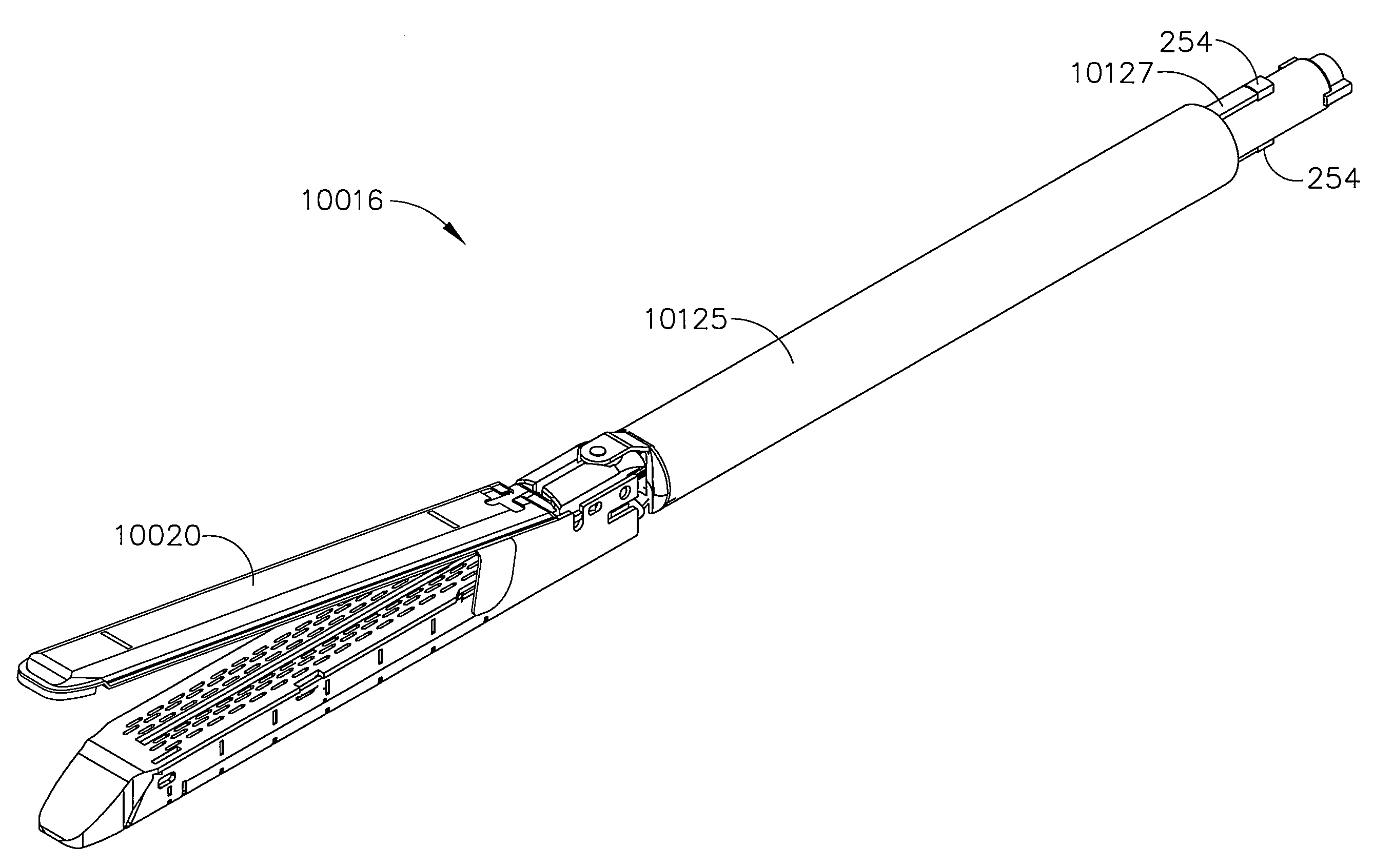
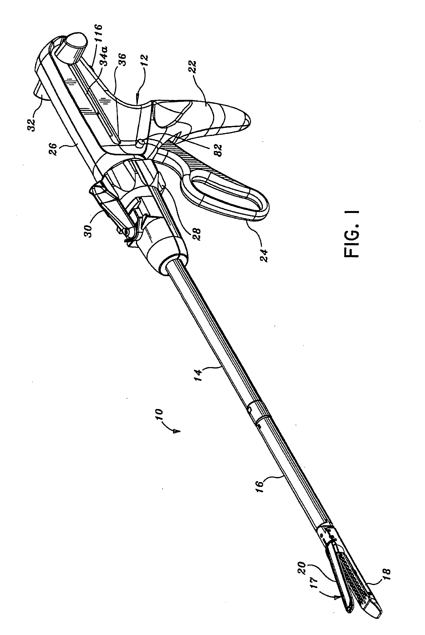
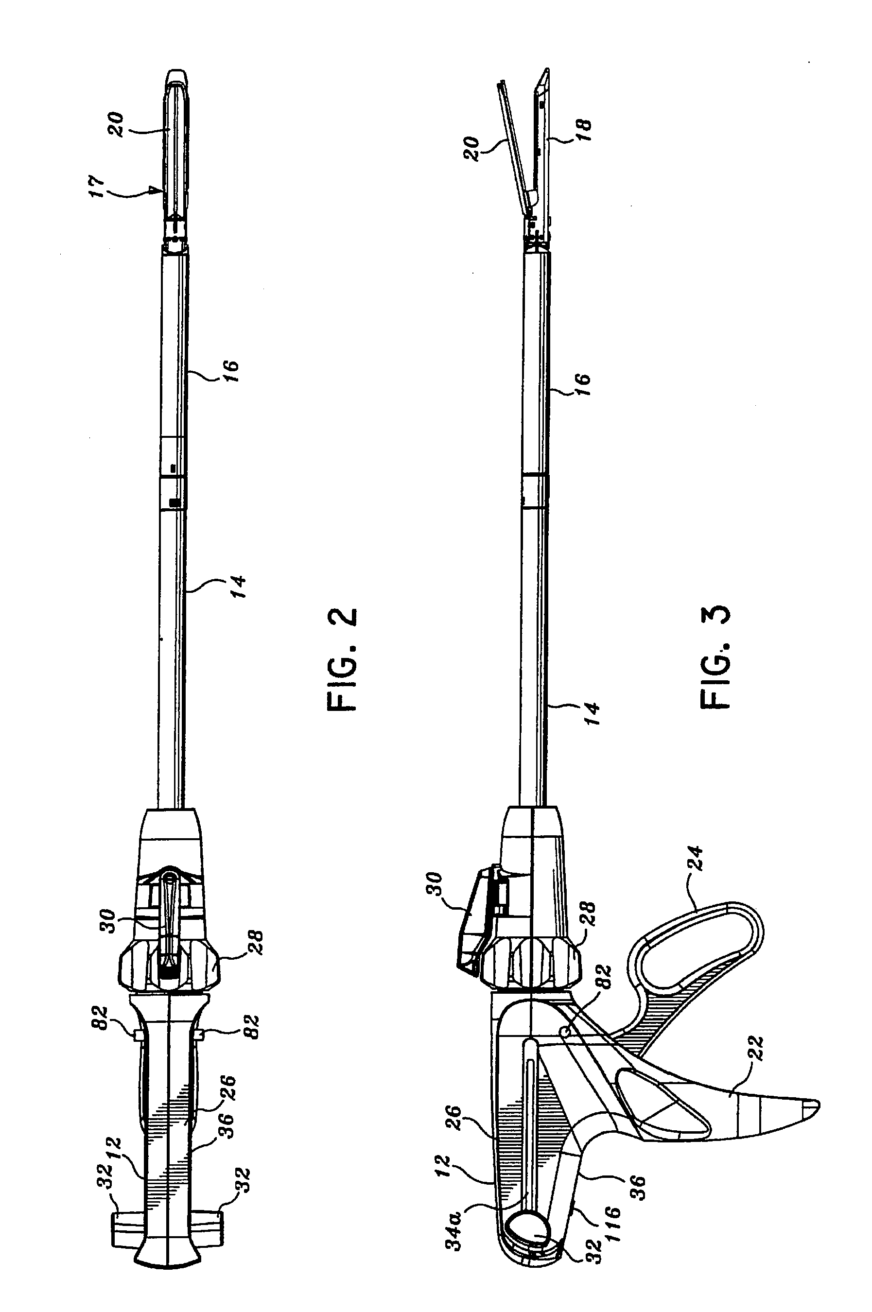
[0010]In accordance with the present disclosure, improvements to a surgical stapling apparatus for sequentially applying a plurality of fasteners to body tissue and incising tissue are provided. In various embodiments, a surgical stapling apparatus includes a handle portion, an elongated body, or shaft, and a disposable loading unit, wherein the disposable loading unit is removably attachable to the elongated body. In at least one embodiment, the elongated body can include a connector portion which can be operably engaged with a connector portion of the disposable loading unit such that, when a trigger of the handle portion is actuated, the trigger can advance a driver within the disposable loading unit to deploy staples from the disposable loading unit and / or incise tissue. In previous surgical stapling devices, though, the disposable loading unit can become detached from the elongate body causing the surgical stapling instrument to malfunction or be rendered inoperable.
[0013]In various embodiments of the present disclosure, such problems can be ameliorated by utilizing a surgical stapling instrument which can clamp the soft tissue, for example, prior to the staples being deployed from the staple cartridge. In various embodiments, a surgical stapling instrument can include an actuator configured to be retracted relative to the distal end of the disposable loading unit where the actuator can be operably engaged with the anvil to rotate the anvil between an open position and a closed position. In at least one embodiment, the actuator can include a cam, where the cam can include an arcuate profile having an apex, and where the apex can be configured to be in contact with the anvil when the anvil is in a closed position. In at least one such embodiment, the anvil can apply a clamping force to the soft tissue prior to the staples being deployed and prevent, or at least inhibit, the soft tissue from flowing, or ‘milking’, out of the distal end of the disposable loading unit.
[0015]After the anvil has been moved into a closed position, a drive beam can be advanced within the disposable loading unit to eject the staples therefrom and / or incise the soft tissue. In various circumstances, the anvil can include a slot defined therein which can be configured to receive at least a portion of the drive beam. In use, the drive beam can apply forces to the anvil which can cause the anvil to elastically and / or plastically deform and, as a result, affect the deployment of the surgical staples into the soft tissue. In various embodiments of the present disclosure, an anvil can include a first member having staple pockets for deforming the staples, a first cover plate secured to the first member, and a second cover plate secured to at least one of the first member and the first cover plate, wherein the first and second cover plates can be configured to support the first member. In at least one embodiment, an anvil can include a first member inserted into a second member, where the second member can be deformed such that the first member can be retained to and support the second member. In other various embodiments, the first member can be press-fit into the second member. In at least one embodiment, as a result of the above, the anvil can be better configured to withstand the forces applied thereto and eliminate, or at least reduce, undesirable deflections within the anvil.
[0017]After the disposable loading unit has been used, or expended, it can be removed from the elongated body of the surgical instrument and a new disposable loading unit can be assembled to the elongated body. Thereafter, the surgical instrument can be reinserted into a surgical site to perform additional steps of a surgical technique. In various circumstances, though, a surgeon, or other clinician, may become confused as to whether a disposable loading unit has been previously expended. In various embodiments of the present disclosure, a disposable loading unit can include a lockout feature which can prevent, or at least inhibit, an expended disposable loading unit from being reassembled to the elongated body of the surgical instrument.
In addition, costs are greater in designing and manufacturing multiple stapler sizes, as opposed to creating a single, multipurpose stapler.
In previous surgical stapling devices, though, the disposable loading unit can become detached from the elongate body causing the surgical stapling instrument to malfunction or be rendered inoperable.
In various circumstances, a portion of the soft tissue can flow, or move, out of the distal end of the disposable loading unit and, as a result, the soft tissue may not be properly treated by the surgical stapling instrument.
In use, the drive beam can apply forces to the anvil which can cause the anvil to elastically and / or plastically deform and, as a result, affect the deployment of the surgical staples into the soft tissue.
Some disposable loading units having large anvils and / or staple cartridges may not fit, or easily fit, through the trocar.
Method used
Image
Click on the blue label to locate the original text in one second.
Reading with bidirectional positioning of images and text.
Examples
Embodiment Construction
[0162]Preferred embodiments of the presently disclosed endoscopic surgical stapling apparatus will now be described in detail with reference to the drawings, in which like reference numerals designate identical or corresponding elements in each of the several views. Those of ordinary skill in the art will understand that the devices and methods specifically described herein and illustrated in the accompanying drawings are non-limiting exemplary embodiments and that the scope of the various embodiments of the present invention is defined solely by the claims. The features illustrated or described in connection with one exemplary embodiment may be combined with the features of other embodiments. Such modifications and variations are intended to be included within the scope of the present invention.
[0163]In the drawings and in the description that follows, the term “proximal”, as is traditional, will refer to the end of the stapling apparatus which is closest to the operator, while the...
PUM
Property
Measurement
Unit
Length
aaaaa
aaaaa
Abstract
In various embodiments, a surgical stapling instrument can include a handle, a shaft extending from the handle, wherein the shaft defines an axis, and a disposable loading unit which is assembled to the shaft in a direction which is transverse to the shaft axis. Such a connection between the disposable loading unit and the shaft can prevent, or at least inhibit, the disposable loading unit from being unintentionally displaced proximally and / or distally relative to the shaft of the surgical instrument. The surgical stapling instrument and / or disposable loading unit can further include a threaded collar and / or detentassembly configured to hold the disposable loading unit in place. In various embodiments, a disposable loading unit can include a lockout feature which can prevent, or at least inhibit, an expended disposable loading unit from being reassembled to the elongated body of the surgical instrument.
Description
BACKGROUND[0001]1. Technical Field[0002]This application relates to a surgical stapling apparatus and, in various embodiments, to an articulating mechanism for use with an endoscopic surgical stapling apparatus for sequentially applying a plurality of surgical fasteners to body tissue and optionally incising fastened tissue.[0003]2. Background of Related Art[0004]Surgical devices wherein tissue is first grasped or clamped between opposing jaw structures and then joined by surgical fasteners are well known in the art. In some instruments, a knife is provided to cut the tissue which has been joined by the fasteners. The fasteners are typically in the form of surgical staples but two part polymeric fasteners can also be utilized.[0005]Instruments for this purpose can include two elongated members which are respectively used to capture or clamp tissue. Typically, one of the members carries a staple cartridge which houses a plurality of staples arranged in at least two lateral rows while...
Claims
Application Information
Patent Timeline
Application Date:The date an application was filed.
Publication Date:The date a patent or application was officially published.
First Publication Date:The earliest publication date of a patent with the same application number.
Issue Date:Publication date of the patent grant document.
PCT Entry Date:The Entry date of PCT National Phase.
Estimated Expiry Date:The statutory expiry date of a patent right according to the Patent Law, and it is the longest term of protection that the patent right can achieve without the termination of the patent right due to other reasons(Term extension factor has been taken into account ).
Invalid Date:Actual expiry date is based on effective date or publication date of legal transaction data of invalid patent.
InventorWEISENBURGH, II, WILLIAM B.MORGAN, JEROME R.MOORE, KYLE P.RANSICK, MARK H.HALL, STEVEN G.TANGUAY, RANDALL J.MESSERLY, JEFFREY D.ROBERTSON, GALEN C.ZWOLINSKI, ANDREW M.SWAYZE, JEFFREY S.HUITEMA, THOMAS W.ARMSTRONG, GLEN A.PARIHAR, SHAILENDRA K.KORVICK, DONNA L.TIMM, RICHARD W.DOLL, KEVIN R.SMITH, BRET W.KELLY, WILLIAM D.KOLATA, RONALD J.UTH, JOSHUA R.SCHEIB, CHARLES J.HUEIL, GEOFFREY C.ORTIZ, MARK S.HOFFMAN, DOUGLAS B.WEIZMAN, PATRICK A.BRUEWER, DEAN B.BLAIR, GREGORY B.SHELTON, IV, FREDERICK E.

