

Connection of an electric motor to a supply network
- Summary
- Abstract
- Description
- Claims
- Application Information
AI Technical Summary
Benefits of technology
Problems solved by technology
Method used
Image

Examples
Embodiment Construction
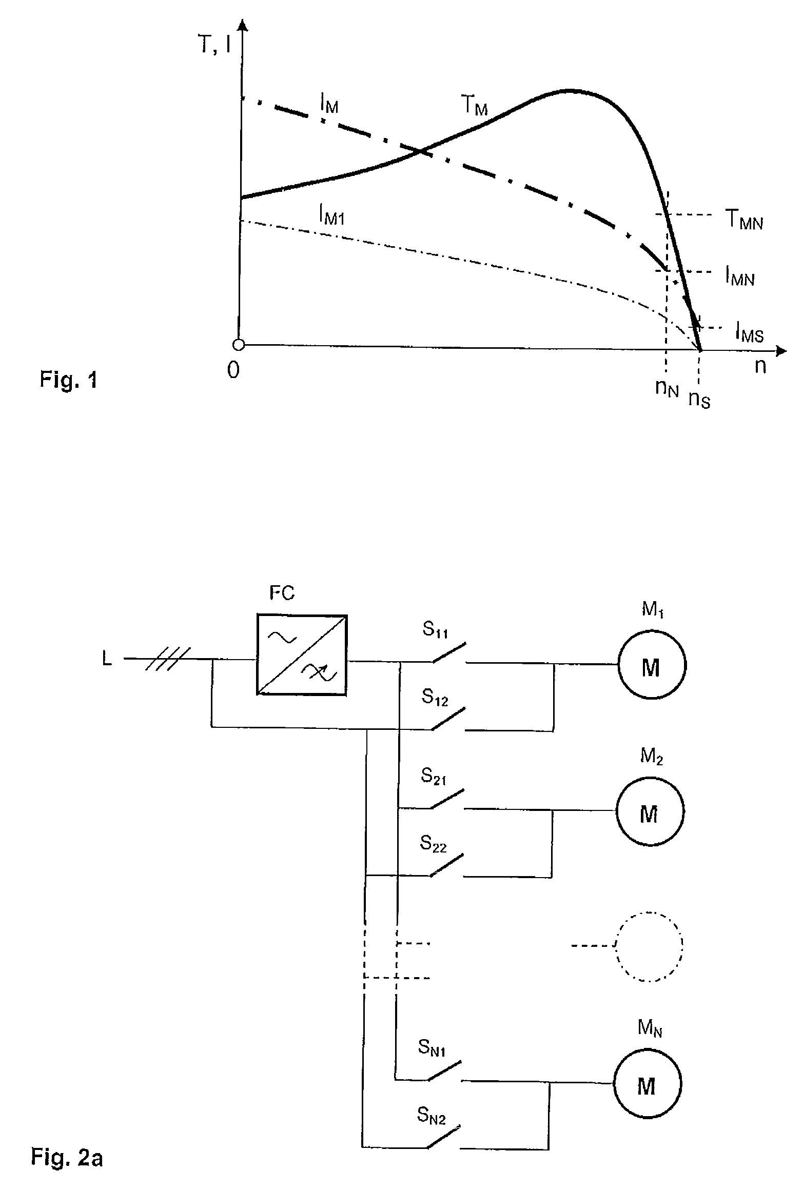
[0021]FIG. 1 presents prior-art characteristic curves typical of the current IM and the torque TM of a squirrel-cage motor supplied with a constant voltage. In the figure the horizontal axis has a speed of rotation n and the vertical axis a torque T and current I. According to the figure, the speed of rotation of the motor at the rated point is nN, the torque TMN and the current IMN, and also the speed of rotation at the so-called synchronous operating point is nS, the torque 0 and the current IMS. At the time of starting, when the speed of rotation is still 0, the current IM is generally many times greater compared to the rated current, which can be a problem from the viewpoint of dimensioning the supply circuit.
[0022]To avoid a large starting current, it is prior art to use a so-called soft starter, which reduces the voltage supplied to the motor when starting. At a lower voltage the characteristic curves of the motor are lower, e.g. in the manner of the current curve IM1 presente...
PUM
 Abstract
Description
Claims
Application Information