
Low-powered RFID tag and method of expanding lifecycle of RFID tag

a low-power, rfid tag technology, applied in the field of rfid tags, can solve the problems of affecting the lifecycle of rfid tags and the difficulty of generating sufficient voltag

Inactive Publication Date: 2008-06-12
ELECTRONICS & TELECOMM RES INST
View PDF12 Cites 51 Cited by
  • Summary
  • Abstract
  • Description
  • Claims
  • Application Information

AI Technical Summary

Benefits of technology

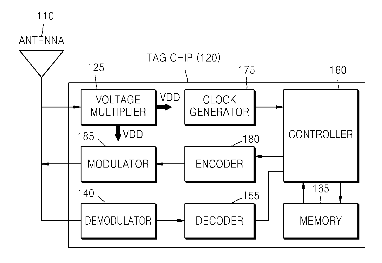
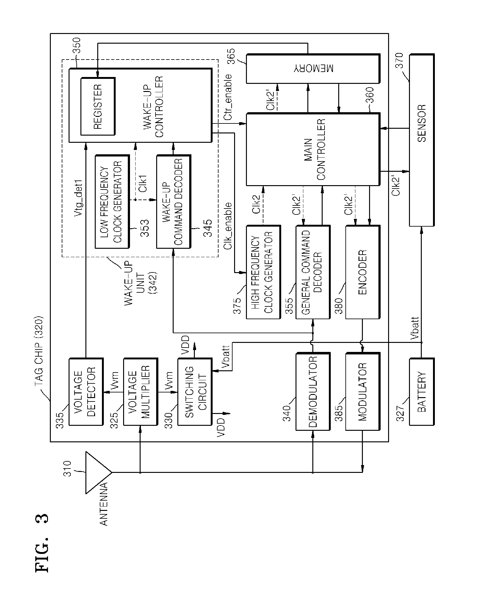
The present invention provides an RFID tag with a wake-up unit that minimizes standby current and a method of waking up the RFID tag. Additionally, the invention provides an RFID tag with a driving unit that expands the lifecycle of a built-in battery and a method of driving the RFID tag. The RFID tag includes a general command decoder, a wake-up command decoder, a main controller, and a wake-up controller. The main controller decodes signals received from an RFID tag reader and executes general commands. The wake-up controller detects a continuous wave in the signal and activates the main controller if the continuous wave matches a predetermined activation code. The invention also includes a built-in battery and a voltage multiplier that rectifies and boosts the voltage of the signal to power the RFID tag. The method of supplying power includes rectifying and boosting the voltage of the signal and applying a higher one between the boosted voltage and the battery voltage to power the RFID tag.

Problems solved by technology

Therefore, when the passive RFID tag is apart from the RFID tag reader by a predetermined distance (about 5 mm) or more, there is a problem in that it is difficult to generate a sufficient voltage.
However, the battery-powered RFID tag has a problem in that the lifecycle of the RFID tag depends on the lifecycle of the battery.

Method used


Image

  • Low-powered RFID tag and method of expanding lifecycle of RFID tag
  • Low-powered RFID tag and method of expanding lifecycle of RFID tag
  • Low-powered RFID tag and method of expanding lifecycle of RFID tag

Examples


Embodiment Construction

[0027]Hereinafter, a face descriptor generating apparatus according to an embodiment of the present invention is described in detail with reference to the accompanying drawings.

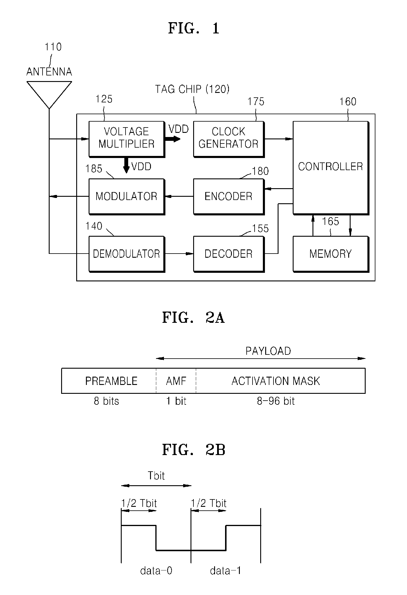
[0028]FIG. 2A shows an activation command which is transmitted from a radio frequency identification (RFID) tag reader to wake up an RFID tag according to an embodiment of the present invention.

[0029]Referring to FIG. 2A, a wake-up command (activation command) includes a preamble, an activation mask flag (AMF), and an activation mask (AMSK). Generally, an activation code stored in the RFID tag has a size of 8 bits to 96 bits. It is determined whether or not the activation code matches with the activation mask of the wake-up command.

[0030]FIG. 2B shows an encoding scheme for the activation command which is transmitted from the RFID tag reader to wake up the RFID tag according to the embodiment of the present invention.

[0031]Referring to FIG. 2B, the wake-up command of FIG. 2A is encoded using Manchester encodi...


PUM


Abstract

A battery-powered RFID tag capable of reducing power consumption and a method of waking up the RFID tag are provided. The battery-powered RFID tag has an activated mode where a general command is detected by decoding a signal received from an RFID tag reader and the general command is executed and a standby mode where the general command is not detected. If a voltage of a continuous wave detected from the signal is equal to or higher than a predetermined voltage or if a wake-up command is detected from the signal, the state of the RFID tag is changed from the standby mode to the activated mode. In addition, the RFID tag is driven by a higher one between the voltage of the continuous wave and a voltage of a built-in battery.

Description

CROSS-REFERENCE TO RELATED PATENT APPLICATION[0001]This application claims the benefit of Korean Patent Application No. 10-2006-0125021, filed on Dec. 8, 2006, in the Korean Intellectual Property Office, the disclosure of which is incorporated herein in its entirety by reference.BACKGROUND OF THE INVENTION[0002]1. Field of the Invention[0003]The present invention relates to a radio frequency identification (RFID) tag, and more particularly, to a battery-powered RFID tag having a wake-up unit capable of expanding lifecycle of a battery, a method of waking up an RFID tag, a power supply device for an RFID tag, and a method therefore.[0004]This work was supported by the IT R&D program of MIC / IITA.[2005-S-106-02, Development of Sensor Tag and Sensor Node Technologies for RFID / USN][0005]2. Description of the Related Art[0006]In a radio frequency identification (RFID) technology, an RFID tag containing identification (ID) unique to a product is attached to the product, and the ID is detec...

Claims


Application Information

Patent Timeline
Patent Type & Authority Applications(United States)
IPC IPC(8): H04B7/00
CPCG06K19/0723Y02B60/50H04W52/0229Y02D30/70G06K19/07G06K17/00
Inventor CHOI, SU NASON, HAE WONYEO, JUNHOJUNG, JAE YOUNGSEO, JONG HYUNCHOI, GIL YOUNGPYO, CHEOL SIGCHAE, JONG SUK
Owner ELECTRONICS & TELECOMM RES INST
Learn More