Charging or discharging apparatus for electrically charging or discharging a capacitor storage type power source adapted to store electric energy in electric double layer capacitors

a capacitor and storage type technology, applied in the direction of several simultaneous battery arrangements, electrical generators, transportation and packaging, etc., can solve the problems of excessive flow, short charge time, and short charge time, so as to reduce the leak current, improve the effective efficiency and suppress the emission of heat of the discharging apparatus

Inactive Publication Date: 2009-11-24
POWER SYST KK
View PDF2 Cites 52 Cited by
  • Summary
  • Abstract
  • Description
  • Claims
  • Application Information

AI Technical Summary

Benefits of technology

[0034]When the upper limit of the withstand current of the parallel monitors of an energy storage type power source is reduced for the purpose of reducing the power loss that arises as a result of bypass operations of the parallel monitors, the charge current needs to be reduced accordingly. Then, a prolonged charge time is required. Problems arise when an attempt is made to minimize the variances of charge voltage. For example, the operation of initializing the electric double layer capacitors has to be repeated frequently. Then, a cumbersome process has to be executed to adjust the operation of switching the constant current charge and the constant power charge and a complex circuit and a complex control operation will be required for such a process to consequently raise the cost.
[0088]Thus, according to the present invention, a suspended discharge condition is determined to turn on / off the power feed circuit of the control power supply circuit so that it is possible to prevent the power accumulated in the electric double layer capacitors of the capacitor storage type power source from being decreased due to the leak currents from the control power supply circuit for controlling electric discharges if the capacitor storage type power source left with the discharging apparatus connected thereto for a long period of time. Additionally, the electric current that flows to the circuits when the power feed circuit is turned off is limited to only the current flowing through the high impedance element so that it is possible to minimize the leak currents that flow in a suspended discharge condition. Therefore, it is possible to improve the effective efficiency of the discharging apparatus and suppress the emission of heat of the discharging apparatus.

Problems solved by technology

If a low power type charge process is employed, the charge current is high when the voltage is low and falls as the full charge condition comes closes but becomes very large in a voltage region close to nil so that it flows excessively.
Then, a prolonged charge time is required.
Problems arise when an attempt is made to minimize the variances of charge voltage.
Then, a cumbersome process has to be executed to adjust the operation of switching the constant current charge and the constant power charge and a complex circuit and a complex control operation will be required for such a process to consequently raise the cost.

Method used


Image

  • Charging or discharging apparatus for electrically charging or discharging a capacitor storage type power source adapted to store electric energy in electric double layer capacitors
  • Charging or discharging apparatus for electrically charging or discharging a capacitor storage type power source adapted to store electric energy in electric double layer capacitors
  • Charging or discharging apparatus for electrically charging or discharging a capacitor storage type power source adapted to store electric energy in electric double layer capacitors

Examples


first embodiment

[0319]Now, the advantages of the above-described first embodiment will be summarized below.

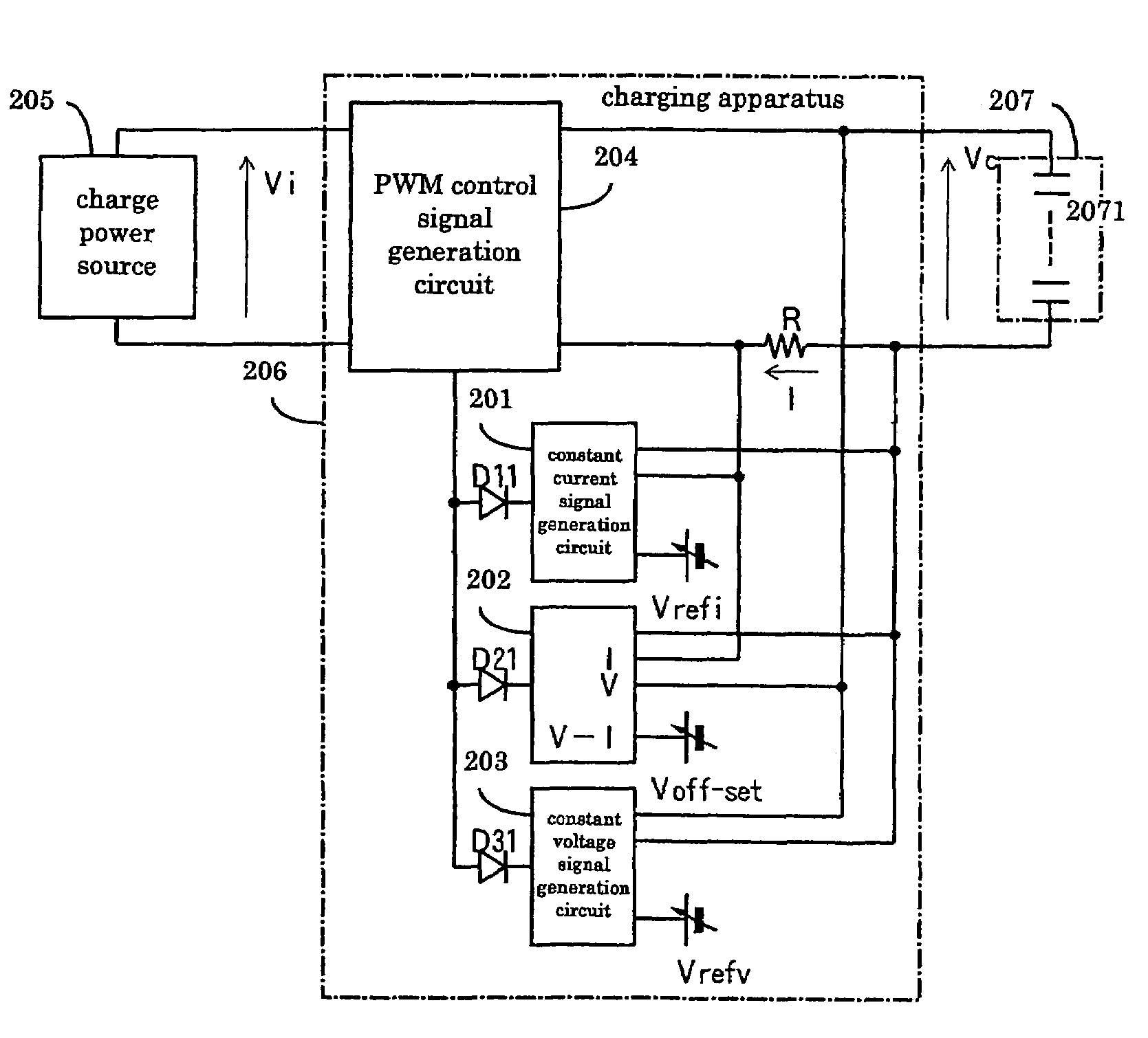
[0320]It is possible to detect the maximum power point only by detecting the current or the voltage of the capacitor side.

[0321]It is possible to detect the maximum power point that includes the efficiency of the power conversion circuit such as the converter section (with the function of following the maximum power point in a controlled manner).

second embodiment

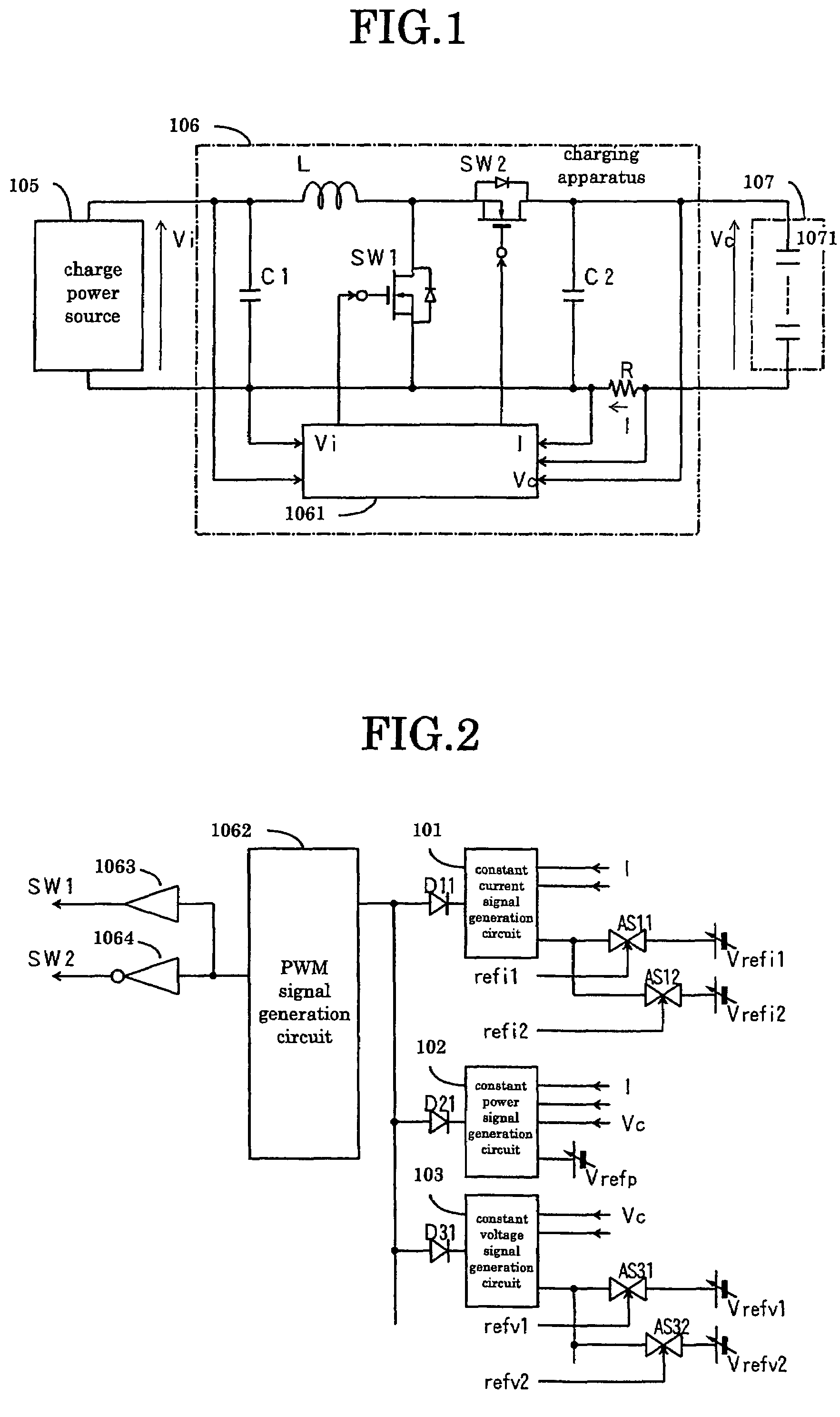
[0322]Additionally, with the second embodiment, it is possible to detect the maximum power point that includes both the efficiency of the power conversion circuit and the charge efficiency of the capacitor section.

[0323]The efficiency can fall remarkably when there is substantially no input to the power conversion circuit. However, according to the present invention, the efficiency is excellent when the output of the solar cells is low because it is possible to detect the maximum power point that includes the efficiency of the power conversion circuit.

[0324]While most known electric cells can display the power charged in the cell, it is not possible to confirm the power actually charged in the cell. For example, when a lead accumulator is electrically charged at an ambient temperature of about 0° C., the rate of the chemical change that takes place falls dramatically if the charge current is flowing (a condition expressed as inactivated) so that the accumulated energy is far less th...


PUM

PropertyMeasurementUnit
charge/discharge efficiencyaaaaaaaaaa
voltageaaaaaaaaaa
voltageaaaaaaaaaa

Abstract

A charging apparatus for electrically charging a capacitor storage type power source comprises a switching circuit for turning on / off the charge current, a current detection circuit for detecting the charge current, a voltage detection circuit for detecting the voltage of power source, a constant current control circuit for outputting an error amplifying signal according to the current value, a power control circuit for outputting an error amplifying signal according to the current value, the voltage value-and a power reference value, a constant voltage control circuit for outputting an error amplifying signal according to the voltage value and a voltage reference value, an OR circuit for selecting one of the error amplifying signals and a control circuit for generating a pulse width modulation signal according to the error amplifying signal output from the OR circuit to turn on / off the switching circuit and control the charge current.

Description

CROSS-REFERENCE TO RELATED APPLICATIONS[0001]This patent application is based upon and claims the benefit of priority from the prior Japanese Patent Applications No. 2006-040764 filed on Feb. 17, 2006, No. 2006-042000 filed on Feb. 20, 2006, No. 2006-042001 filed on Feb. 20, 2006, No. 2006-043335 filed on Feb. 21, 2006, No. 2006-081999 filed on Mar. 24, 2006, No. 2006-082096 filed on Mar. 24, 2006, No. 2006-083402 filed on Mar. 24, 2006, No. 2006-113987 filed on Apr. 18, 2006, No. 2006-209849 filed on Aug. 1, 2006 and No. 2006-231485 filed on Aug. 29, 2006, the entire contents of which are incorporated herein by reference.BACKGROUND OF THE INVENTION[0002](A first aspect of the invention) This invention relates to a charging apparatus for a capacitor storage type power source for electrically charging a capacitor storage type power source storing electric energy in electric double layer capacitors.[0003]The terminal voltages can fluctuate to a large extent in a high voltage and large...

Claims


Application Information

Patent Timeline
Patent Type & Authority Patents(United States)
IPC IPC(8): H01M10/46
CPCH02J7/0016H02J7/345H02J7/0065H02J2207/20
Inventor SHIMIZU, MASAAKIMITSUI, KATSUJISHIMIZU, MASAHIKOYAMAMOTO, SHINICHISHIMIZU, ATSUSHISHINOTSUKA, MASAHIKOYAMAGISHI, MASAAKITSUJI, HIROSHI
Owner POWER SYST KK
Why Eureka
Try Eureka