Magnetoresistance effect element and magnetic random access memory

a technology of magnetic random access and effect element, which is applied in the manufacture of flux-sensitive heads, instruments, record information storage, etc., can solve the problems of insufficient write current amount, difficulty in achieving large memory capacity, and increased current amount required for writing, etc., to achieve high-speed writing, reduce current required for writing, and large capacity

Active Publication Date: 2009-10-01
KIOXIA CORP
View PDF4 Cites 49 Cited by
  • Summary
  • Abstract
  • Description
  • Claims
  • Application Information

AI Technical Summary

Benefits of technology

[0009]The present invention has been made in view of these circumstances, and an object thereof is to provide a magnetoresistance effect element and a magnetic random access memory that can minimize the current required for writing, perform high-speed writing, and have large capacity.
[0010]A magnetoresistance effect element according to a first aspect of the present invention includes: a first ferromagnetic layer having invariable magnetization perpendicular to a film plane; a second ferromagnetic layer having variable magnetization perpendicular to the film plane; a first nonmagnetic layer interposed between the first ferromagnetic layer and the second ferromagnetic layer; a third ferromagnetic layer provided on an opposite side of the second ferromagnetic layer from the first nonmagnetic layer, and having variable magnetization parallel to the film plane; and a second nonmagnetic layer interposed between the second ferromagnetic layer an

Problems solved by technology

By the current field write technique, however, the current amount required for writing becomes greater as the memory cells become smaller.
As a result, it becomes difficult to achie

Method used


Image

  • Magnetoresistance effect element and magnetic random access memory
  • Magnetoresistance effect element and magnetic random access memory
  • Magnetoresistance effect element and magnetic random access memory

Examples


first embodiment

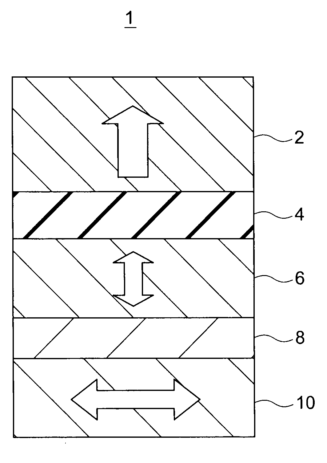
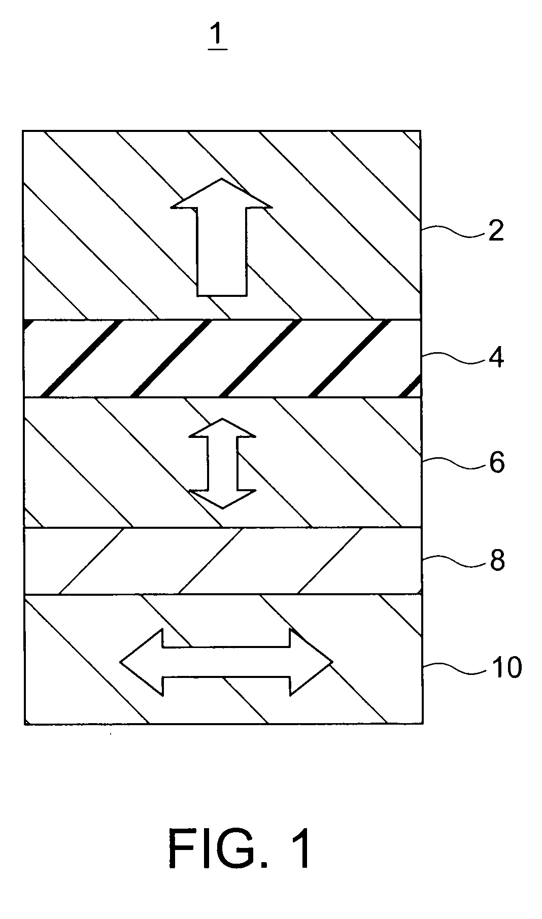
[0023]FIG. 1 shows a magnetoresistance effect element in accordance with a first embodiment 1 of the present invention. The magnetoresistance effect element of this embodiment includes an invariable magnetization layer (reference magnetization layer) 2, a tunnel barrier layer 4, a magnetic recording layer 6, a spacer layer 8, and a magnetization oscillating layer 10. The invariable magnetization layer 2 includes a ferromagnetic layer having a magnetization direction that is substantially perpendicular to the film plane and is invariable before and after application of a current to the magnetoresistance effect element 1. The tunnel barrier layer 4 is formed with an oxide containing an element selected from the group of Mg, Al, Ti, Hf, and the likes, from which a desired magnetoresistance effect variation can be obtained by tunneling electrons. More specifically, magnesium oxide, aluminum oxide, or the like can be used as the tunnel barrier layer 4. The magnetic recording layer 6 incl...

second embodiment

[0035]FIG. 8 shows a magnetoresistance effect element in accordance with a second embodiment of the present invention. The magnetoresistance effect element 1 of this embodiment is the same as the magnetoresistance effect element 1 of the first embodiment shown in FIG. 1, except that the magnetization oscillating layer 10 has a stacked structure of ferromagnetic layers 10a and 10c that are ferromagnetically coupled and have a nonmagnetic layer 10b interposed in between, instead of a single-layer ferromagnetic layer having a magnetization direction parallel to the film plane. The magnetization direction of each of the ferromagnetic layers 10a and 10c are parallel to the film plane.

[0036]If the magnetic material having magnetization parallel to the film plane is formed in a circular shape, a square shape, or a square-like shape having each corner rounded in a magnetization oscillating layer formed with a single-layer ferromagnetic film, a reflux domain structure might be formed. The re...

third embodiment

[0038]FIG. 9 shows a magnetoresistance effect element in accordance with a third embodiment of the present invention. The magnetoresistance effect element 1 of this embodiment differs from the magnetoresistance effect element 1 of the first embodiment shown in FIG. 1, in that the magnetic recording layer 6 is replaced with a stacked structure of an ordered alloy layer 6a or an alloy layer 6a and an alloy layer 6b. The ordered alloy layer 6a has a L10 crystalline structure containing at least one element selected from the group of Fe, Co, and Ni, and at least one element selected from the group of Pt and Pd. The alloy layer 6a is formed with an alloy having a hexagonal crystalline structure containing at least one element selected from the group of Fe, Co, and Ni, and at least one element selected from the group of Cr, Ta, Pt, and Pd, and has magnetic anisotropy in a direction substantially perpendicular to the film plane. The alloy layer 6b contains at least one element selected fro...


PUM


Abstract

A magnetoresistance effect element includes: a first ferromagnetic layer having invariable magnetization perpendicular to a film plane; a second ferromagnetic layer having variable magnetization perpendicular to the film plane; a first nonmagnetic layer interposed between the first ferromagnetic layer and the second ferromagnetic layer; a third ferromagnetic layer provided on an opposite side of the second ferromagnetic layer from the first nonmagnetic layer, and having variable magnetization parallel to the film plane; and a second nonmagnetic layer interposed between the second and third ferromagnetic layers. Spin-polarized electrons are injected into the second ferromagnetic layer by flowing a current in the direction perpendicular to the film planes between the first and third ferromagnetic layers, precession movement is induced in the magnetization of the third ferromagnetic layer by injecting the spin-polarized electrons, and a microwave magnetic field of a frequency corresponding to the precession movement is applied to the second ferromagnetic layer.

Description

CROSS-REFERENCE TO RELATED APPLICATION[0001]This application is based upon and claims the benefit of priority from prior Japanese Patent Application No. 2008-78420 filed on Mar. 25, 2008 in Japan, the entire contents of which are incorporated herein by reference.BACKGROUND OF THE INVENTION[0002]1. Field of the Invention[0003]The present invention relates to a magnetoresistance effect element and a magnetic random access memory.[0004]2. Related Art[0005]Various types of solid magnetic memories have been developed. In recent years, magnetic random access memories (MRAM) including magnetoresistance effect elements each exhibiting the giant magnetoresistive (GMR) effect have been suggested, and, particularly, attention is drawn to magnetic random access memories using ferromagnetic tunnel junctions each exhibiting the tunnel magnetoresistive (TMR) effect.[0006]A MTJ (Magnetic Tunnel Junction) element of a ferromagnetic tunnel junction is formed with a three-layer film including a first ...

Claims


Application Information

Patent Timeline
IPC IPC(8): G11B5/33
CPCH01L43/08H01L27/226G11C11/161G11C11/1675H10B61/20H10N50/10G11C11/15H10N50/01
Inventor NAKAYAMA, MASAHIKOKAI, TADASHIIKEGAWA, SUMIOYODA, HIROAKIKISHI, TATSUYA
Owner KIOXIA CORP
Why Eureka
Try Eureka