Electrooptical device, electronic device, and control method of electrooptical device

a control method and electrooptical technology, applied in static indicating devices, non-linear optics, instruments, etc., can solve the problems of deteriorating display quality, longer load and writing time than ordinary movie drives, and inability to perform desired writing in required tim

Active Publication Date: 2017-09-21
SEIKO EPSON CORP
View PDF3 Cites 2 Cited by
  • Summary
  • Abstract
  • Description
  • Claims
  • Application Information

AI Technical Summary

Benefits of technology

[0009]An advantage of some aspects of the invention is to provide an electrooptical device that can write a desired voltage even in a case of applying precharge signals to all data lines at the same time and an electronic device provided with the electrooptical device.
[0014]In this case, the electrooptical device may further include: a voltage selection unit that is provided between the connection unit and the voltage switching unit and selects one of a high-potential precharge voltage and a low-potential precharge voltage to be supplied to the connection unit, and the control unit may control the voltage selection unit to select the low-potential precharge voltage in a first precharge period in the second period and select the high-potential precharge voltage in a second precharge period in the second period. According to the aspect, since the low-potential precharge voltage is written in the data lines in the first precharge period, occurrence of vertical crosstalk is prevented. In addition, since the high-potential precharge voltage is written in the data lines in the second precharge period, the high-potential precharge voltage can be written in the data lines before the data line drive circuit writes the first voltage in the pixels. Therefore, it is possible to shorten the writing time of the first voltage in the pixels by the data line drive circuit.
[0016]According to another aspect of the invention, there is provided an electronic device including: the aforementioned electrooptical device. According to such an electronic device, the second voltage is written in the data lines at a high speed even if the number of data lines increases in response to an increase in resolution since the second voltage is output from the external voltage output unit in a display device such as a liquid crystal display. As a result, it is possible to improve image quality.

Problems solved by technology

Incidentally, in a case where image signals are not sufficiently supplied, for example, in a case where sufficient time for supplying image signals to the respective pixels cannot be secured, the respective pixels cannot accurately display the tones designated by the image signals, and display quality may deteriorate.
However, since the precharge signal is simultaneously applied to all the data lines by using the back porch portion, a load becomes larger and writing time becomes longer as compared with ordinary movie drive.
Such an influence significantly appears, and desired writing cannot be performed in required time in some cases when the precharge signal is applied by a high-resolution low-power-consumption driver.

Method used


Image

  • Electrooptical device, electronic device, and control method of electrooptical device
  • Electrooptical device, electronic device, and control method of electrooptical device
  • Electrooptical device, electronic device, and control method of electrooptical device

Examples


modification examples

[0075]The invention is not limited to the aforementioned embodiments, and for example, various modifications descried below can be made. It is a matter of course that the respective embodiments and the respective modification examples may be appropriately combined.

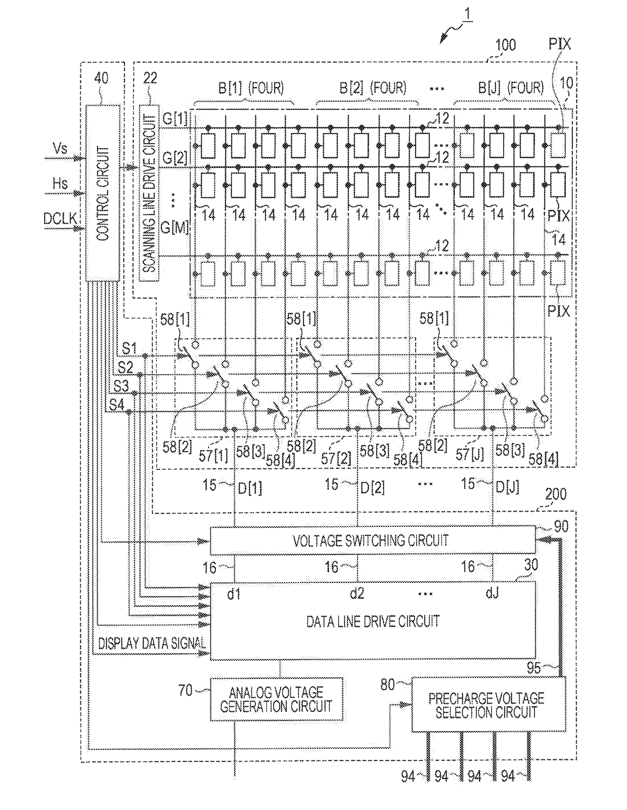
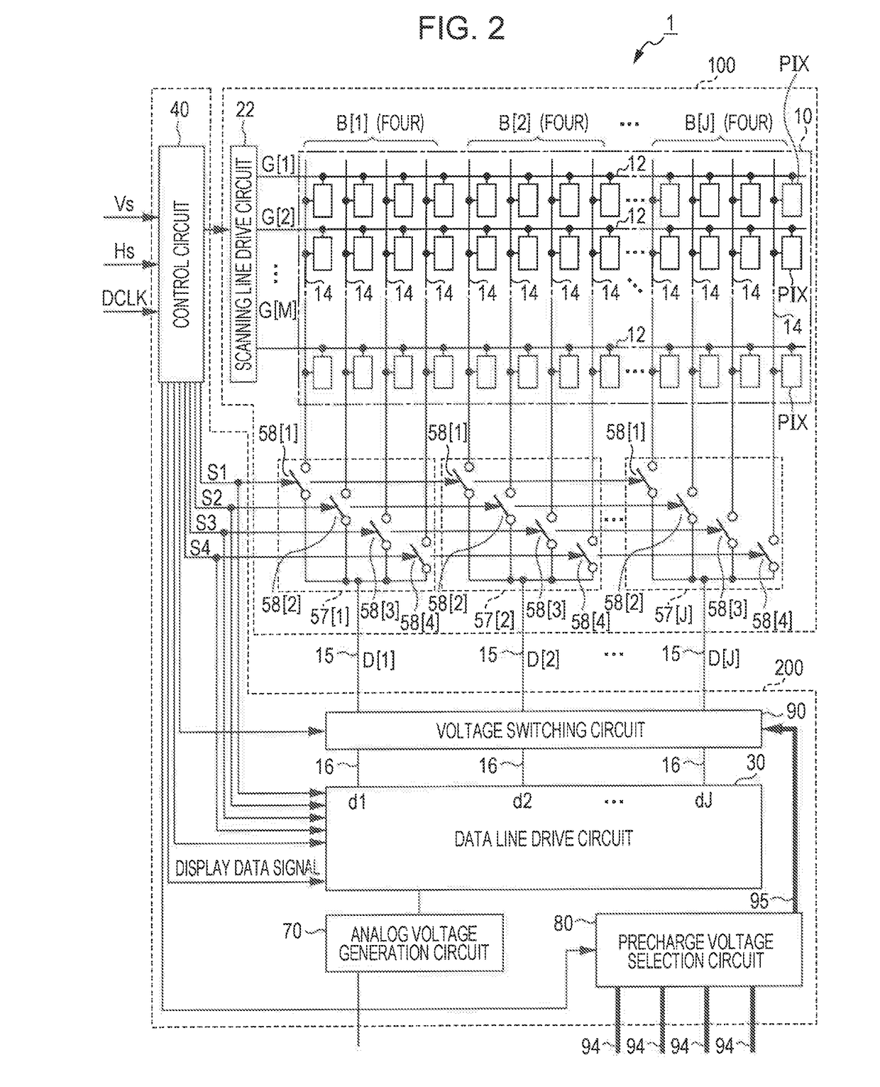
[0076](1) The aforementioned embodiment is an example in which polarity reversion drive is performed, two-stage precharge is performed, and the four precharge voltages are used as the precharge voltages. However, two precharge voltage may be used as the precharge voltages in an example in which the two-stage precharge is not performed even though the polarity reversion drive is performed or in an example in which the two-stage precharge is performed without performing the polarity reversion drive. In an example in which neither the polarity reversion drive nor the two-stage precharge are performed, one precharge voltage may be used as the precharge voltage. In such a case, the precharge voltage selection circuit 80 may be ...

application examples

[0079]The invention can be utilized for various electronic devices. FIGS. 7 to 9 illustrate specific forms of the electronic devices as targets of applications of the invention.

[0080]FIG. 7 is a perspective view of a portable personal computer that employs the electrooptical device. A personal computer 2000 includes the electrooptical device 1 that displays various images and a main body 2010 with a power switch 2001 and a keyboard 2002 installed thereon.

[0081]FIG. 8 is a perspective view of a mobile phone. A mobile phone 3000 includes a plurality of operation buttons 3001, scroll buttons 3002, and the electrooptical device 1 that display various images. By operating the scroll buttons 3002, a screen displayed on the electrooptical device 1 is scrolled. The invention can also be applied to such a mobile phone.

[0082]FIG. 9 is a diagram schematically illustrating a configuration of a projection-type display apparatus (three-plate projector) 4000 that employs the electrooptical device....


PUM


Abstract

A precharge voltage terminal as a connection unit that is for connection with an external precharge voltage output unit that outputs a precharge voltage, a voltage switching circuit that is connected to a data line drive circuit and the precharge voltage terminal in an input stage, is connected to data lines in an output stage, and switches a connection target of the data lines between the data line drive circuit and the precharge voltage terminal, and a control circuit that controls the voltage switching circuit such that the connection target of the data lines is switched to the precharge voltage terminal and the precharge is supplied to the data lines in a fly-back period before a tone display period in which a voltage of an image signal is supplied to pixels via the data lines are provided.

Description

BACKGROUND[0001]1. Technical Field[0002]The present invention relates to technical fields of an electrooptical device such as a liquid crystal device and an electronic device provided with the electrooptical device, such as a liquid crystal projector.[0003]2. Related Art[0004]Electrooptical devices that use liquid crystal elements to display images have widely been developed. According to such electrooptical devices, the transmittance of liquid crystals provided in the respective pixels is controlled to be a transmittance in accordance with designated tones of image signals by supplying the image signals for designating the display tones of the respective pixels to the respective pixels via data lines, and in doing so, the respective pixels are made to display the tones designated by the image signals.[0005]Incidentally, in a case where image signals are not sufficiently supplied, for example, in a case where sufficient time for supplying image signals to the respective pixels canno...

Claims


Application Information

Patent Timeline
Patent Type & Authority Applications(United States)
IPC IPC(8): G09G3/36
CPCG09G3/3696G09G3/3677G09G2310/061G09G2310/0291G09G2310/0248G09G3/3688G02F1/13454G09G3/3648G09G2310/0297G09G2310/063G09G2330/02
Inventor YONEMOCHI, AKIHIKO
Owner SEIKO EPSON CORP
Why Eureka
Try Eureka