Pattern writing apparatus and pattern writing method

Active Publication Date: 2007-03-13
DAINIPPON SCREEN MTG CO LTD
View PDF28 Cites 2 Cited by
  • Summary
  • Abstract
  • Description
  • Claims
  • Application Information

AI Technical Summary

Benefits of technology

[0013]For most efficient pattern writing, the travel distance of the irradiation region group in the sub-scanning direction in one intermittent movement is made approximately equal to the width of one side of the rectangular region in the sub-scanning direction, the one side extending approximately along the sub-scanning direction. That is the equation. A=B×cos θ is satisfied, where A is the travel distance of the irradiation region group in the sub-scanning direction in one intermittent movement, B is the

Problems solved by technology

However, there are technical limitations to what we can do to shorten such times. Thus, it is not easy to drive the spatial light modulator at higher speed for faster pattern writing.
However, addressing and writing data into the blocks is generally performed line b

Method used


Image

  • Pattern writing apparatus and pattern writing method
  • Pattern writing apparatus and pattern writing method
  • Pattern writing apparatus and pattern writing method

Examples


Embodiment Construction

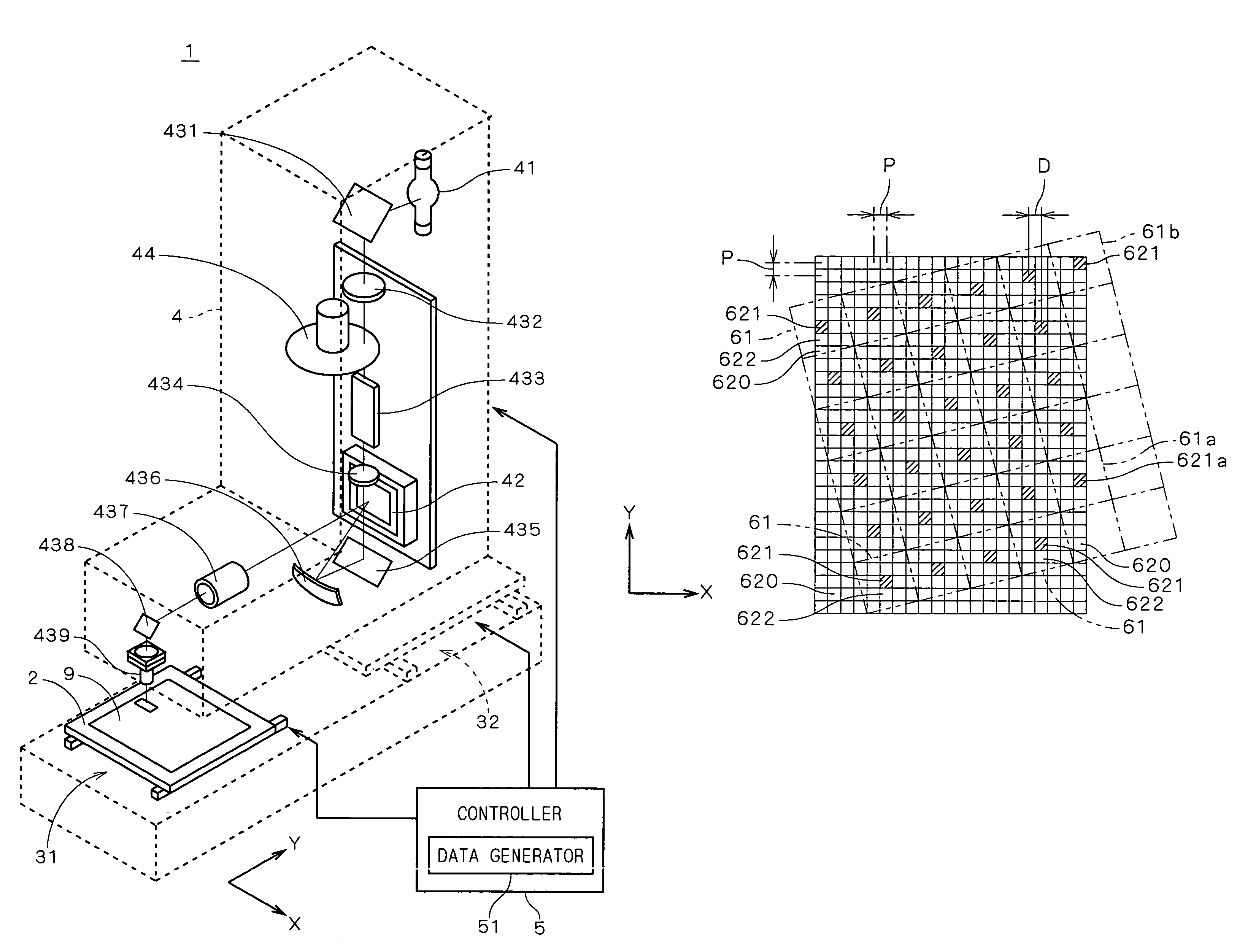
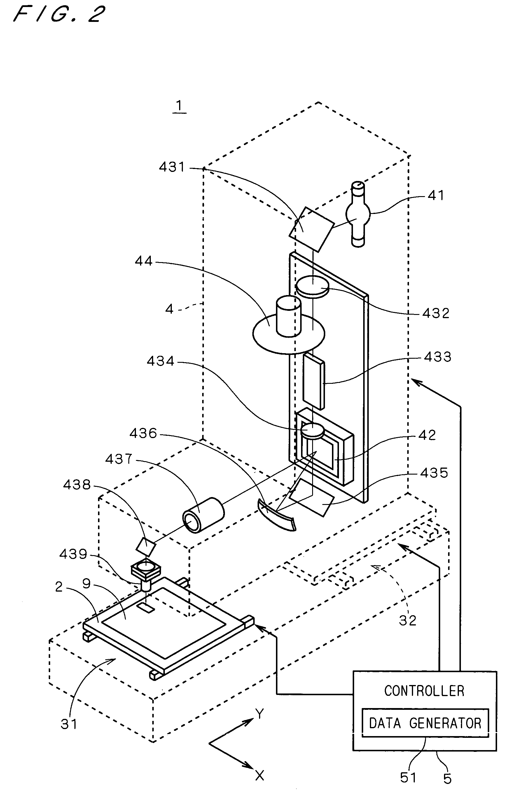
[0032]FIG. 2 is a view showing a structure of a pattern writing apparatus 1 according to one preferred embodiment of the present invention. In FIG. 2, part of the apparatus is shown by dashed lines for illustration of the internal structure of the apparatus. The pattern writing apparatus 1 comprises a stage 2 holding a substrate (e.g., a substrate for a printed circuit board) 9 on which a photoresist film is formed, a stage moving mechanism 31 for moving the stage 2 in the Y direction in FIG. 2, a head 4 emitting a light beam toward the substrate 9, a head moving mechanism 32 for moving the head 4 in the X direction in FIG. 2, and a controller 5 including a data generator 51 generating writing data inputted into the head 4.

[0033]The head 4 includes a light source 41 which is a lamp for emitting light, and a DMD 42 having an array of a plurality of micromirrors, the orientations of which are individually changed. The micromirror group reflects a light beam from the light source 41 to...


PUM


Abstract

A pattern writing apparatus for writing a pattern on a photosensitive material comprises a head provided with a DMD having a micromirror group which modulates reflected light, a stage holding a substrate, and mechanisms for moving the head and the stage relative to each other. In the pattern writing apparatus, for pattern writing, an irradiation region group on a substrate, which corresponds to the micromirror group of the DMD, is scanned in a main scanning direction that is angled relative to the direction of arrangement of the irradiation region group. The irradiation region group is also intermittently moved in the sub-scanning direction by a distance shorter than the width of the irradiation region group in the sub-scanning direction, for pattern writing of the entire substrate.

Description

BACKGROUND OF THE INVENTION[0001]1. Field of the Invention[0002]The present invention relates to a technique for writing a pattern by light irradiation on a photosensitive material.[0003]2. Description of the Background Art[0004]Conventionally well known are techniques for applying a light beam modulated by a spatial light modulator such as a digital micromirror device (DMD) onto a photoresist film formed on a substrate such as a semiconductor substrate or a printed circuit board.[0005]Japanese Patent Application Laid-open No. 62-21220 discloses a technique for writing a fine pattern by applying a light beam which is spatially modulated by a micromirror group of a DMD onto a photosensitive material while moving the photosensitive material and controlling a signal given to the DMD.[0006]Also, Japanese Patent Application Laid-open No. 2001-133893 suggests a technique for writing a finer pattern by tilting an image formed by a DMD on a photosensitive material at 45 degrees relative to ...

Claims


Application Information

Patent Timeline
IPC IPC(8): G03B27/54G03F7/20H01L21/027
CPCG03B27/54
Inventor SHIROTA, HIROYUKI
Owner DAINIPPON SCREEN MTG CO LTD
Why Eureka
Try Eureka