Rotationally Stabilized Contact Lenses and Methods for their Design

a technology of contact lenses and rotating stabilizers, applied in the field of contact lenses, can solve the problems of disadvantageous symmetric stabilization zones, use of these lenses, and inclination of the eye to rota

Active Publication Date: 2009-09-10
JOHNSON & JOHNSON VISION CARE INC
View PDF56 Cites 65 Cited by
  • Summary
  • Abstract
  • Description
  • Claims
  • Application Information

AI Technical Summary

Problems solved by technology

The use of these lenses is problematic in that the lenses must be maintained at a specific orientation while on the eye to be effective.
However, once the lens is positioned, it tends to rotate on the eye due to the forces exerted on the lens by the eyelids during blinking.
The symmetric stabilization zones are disadvantageous because one eyelid, the upper eyelid, for example, will strike one end of a stabilization zone before it strikes the other stabilization zone.
This results in tilting of the lens moving it away from the orientation that is sought to be maintained.

Method used


Image

  • Rotationally Stabilized Contact Lenses and Methods for their Design
  • Rotationally Stabilized Contact Lenses and Methods for their Design
  • Rotationally Stabilized Contact Lenses and Methods for their Design

Examples


example 1

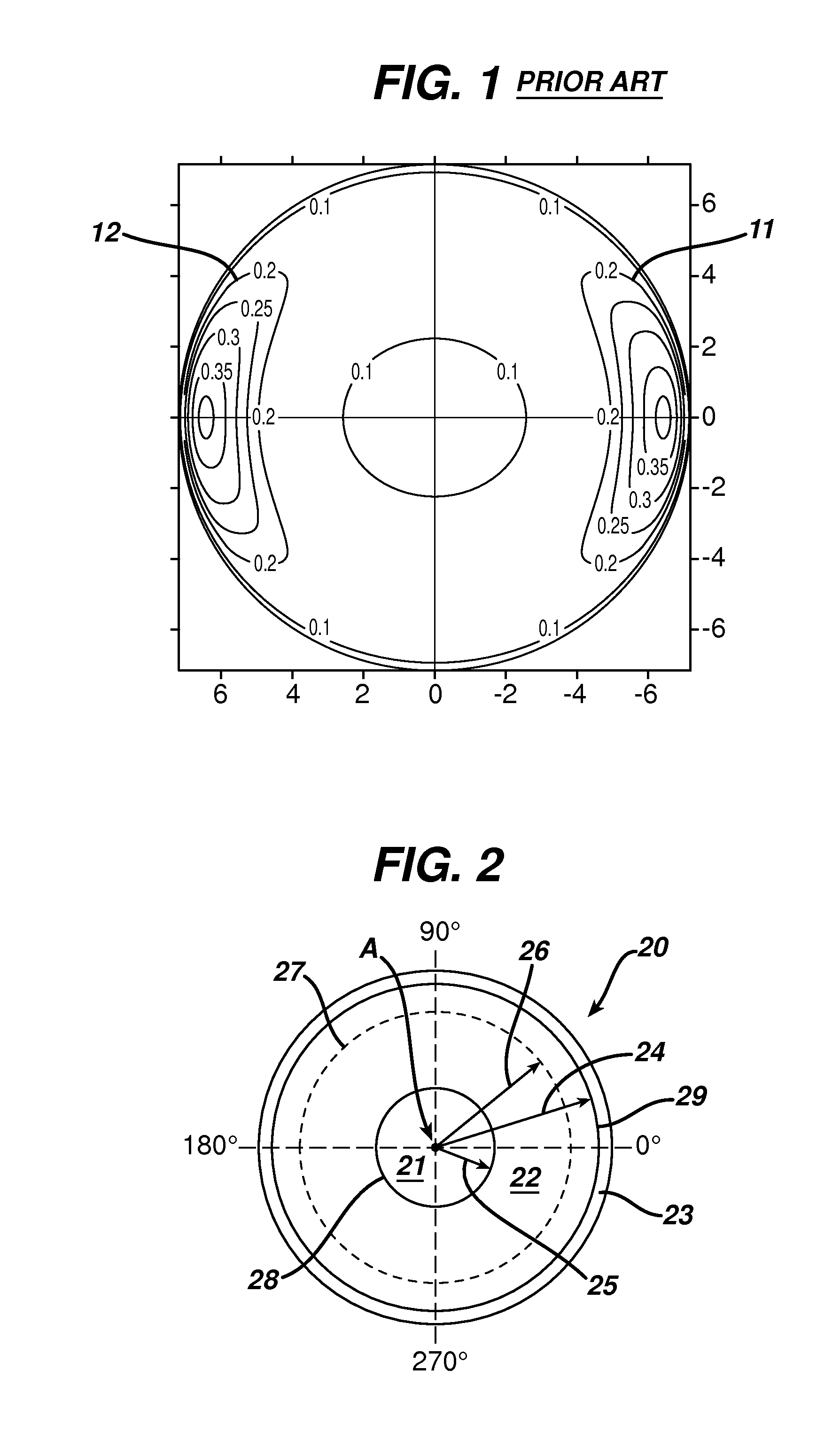
[0045]A prior art contact lens, shown in FIG. 1, is designed having a sphere power of −3.00 diopters, a cylinder power of −0.75 diopters and a cylinder axis of 180 degrees. The dimensional parameters of the lens features and stabilization zones are shown in Table 2 as Example 1. Also, and as shown in FIG. 1, the lens has two, vertically and horizontally symmetric thick zones in the lens periphery. In FIG. 5 is shown that when the lens is rotated off axis by 45 degrees, it returns to within 5 degrees of the stable position 0 in 33 seconds. In FIG. 6 is shown that the lens maintains a centration positions (within 0.2 mm) during the return to a stable orientation and achieves a stable value in 26 seconds. The value within 0.2 mm is a clinically acceptable amount of decentration from a visual performance viewpoint. Thus, during rotation back to a stable position, a lens should not decanter beyond 0.2 mm from zero or vision will be impacted.

TABLE 1ULALLAULPLLP−4.41 degrees1.06 degrees3.7...

example 2

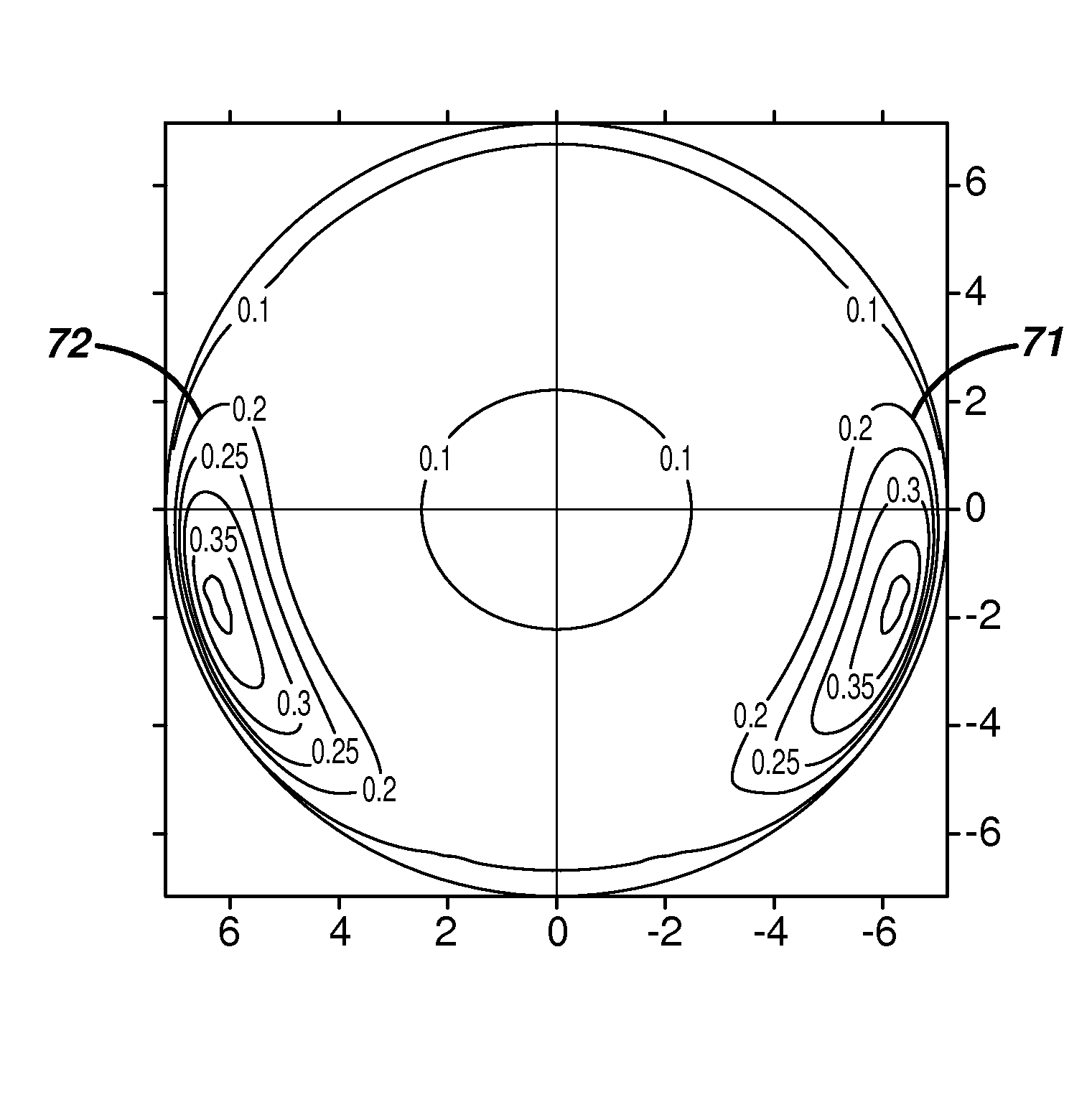
[0046]A lens with sphere power of −3.00 diopters, a cylinder power of −0.75 diopters and a cylinder axis of 180 degrees and a customized stabilization zone is designed according to the method of the invention using the ocular measurement parameters of Table 1 and lens dimensional parameters shown as Example 2 in Table 2 below. By “nasal” and “temporal” in Table 2 is meant the side of the lens that will be on the nasal and temporal side of the lens, respectfully. FIG. 7 depicts the front surface of the lens in which stabilization zones 71 and 72 are asymmetric.

[0047]In FIG. 5 is shown that, when the lens is rotated off axis by 45 degrees, it returns to a stable position (within 5 degrees) in 16 seconds. In FIG. 6 is shown that the lens maintains an acceptable centration position (within 0.2 mm) during the return to a stable orientation and achieves a stable value in 15 secs. These values are a significant improvement in comparison to the lens of Example 1.

TABLE 2Example 1Example 2Len...


PUM


Abstract

The invention provides dual stabilization zones that interact with an individual's eyelids so that at least the upper eyelid strikes both stabilization zones of a lens at the same time. The stabilized lenses of the invention maintain their on-eye orientation better as compared to conventionally stabilized lenses.

Description

FIELD OF THE INVENTION[0001]The invention relates to contact lenses. In particular, the invention provides contact lenses in which the rotational stability is asymmetric.BACKGROUND OF THE INVENTION[0002]It is known that correction of certain optical defects can be accomplished by imparting non-spherical corrective characteristics to one or more surfaces of a contact lens such as cylindrical, bifocal, multifocal, and wavefront corrective characteristics. Additionally, lenses with non-rotationally symmetric tinted patterns, back surfaces that match corneal topography, and lenses with off-set optic zones are known. The use of these lenses is problematic in that the lenses must be maintained at a specific orientation while on the eye to be effective. When such a lens is first placed on the eye, it must automatically position, or auto-position, itself and then maintain that position over time. However, once the lens is positioned, it tends to rotate on the eye due to the forces exerted o...

Claims


Application Information

Patent Timeline
Patent Type & Authority Applications(United States)
IPC IPC(8): G02C7/04
CPCG02C7/048G02C7/04
Inventor CLUTTERBUCK, TIMOTHY A.CHEHAB, KHALEDMENEZES, EDGAR V.FRANKLIN, STEVEN E.HENDRIKS, CORNELIS P.POTZE, WILLEM
Owner JOHNSON & JOHNSON VISION CARE INC
Why Eureka
Try Eureka