Magnetic vane ejection for a rotary vane air motor

a magnetic vane and air motor technology, applied in the direction of machines/engines, liquid fuel engines, positive displacement liquid engines, etc., can solve the problems of reducing the maximum rotor speed, rotary vane, use of springs or pins for ejecting the vanes outward,

Inactive Publication Date: 2009-09-24
GAST MFG
View PDF5 Cites 5 Cited by
  • Summary
  • Abstract
  • Description
  • Claims
  • Application Information

AI Technical Summary

Benefits of technology

[0006]In satisfaction of the aforenoted needs, an improved rotary vane pump is disclosed which comprises: a rotor disposed within a casing that comprises a cavity having an inlet and an outlet. The rotor includes at least one radial slot and at least one vane carried by the radial slot. The vane comprises an inner edge directed towards a central axis of the rotor and an outer edge directed towards the casing. The inner edge is permanently magnetized with a first polarity. The slot in the rotor comprises an inner wall that abuttingly engages or faces the inner edge of the vane when the vane is fully received within the slot. The inner wall of the slot is permanently magnetized with a second polarity opposite to the first polarity so that the inner edge of the vane and inner wall of the slot repel each other thereby biasing the vane radially outwards.

Problems solved by technology

One problem associated with rotary vane pumps or rotary vane pumps is the use of springs or pins for ejecting the vanes outward.
The use of springs or pins for biasing vane movement requires lubrication, reduces maximum rotor speed and limits the time between service or maintenance because of the fatigue or failure rate of the pin and spring mechanisms.
Also, using pins and springs to bias the vanes outward provides a relatively uncontrolled contact forced between the vanes and the internal surface of the cavity and places a limit on rotor speed.

Method used


Image

  • Magnetic vane ejection for a rotary vane air motor
  • Magnetic vane ejection for a rotary vane air motor
  • Magnetic vane ejection for a rotary vane air motor

Examples


Embodiment Construction

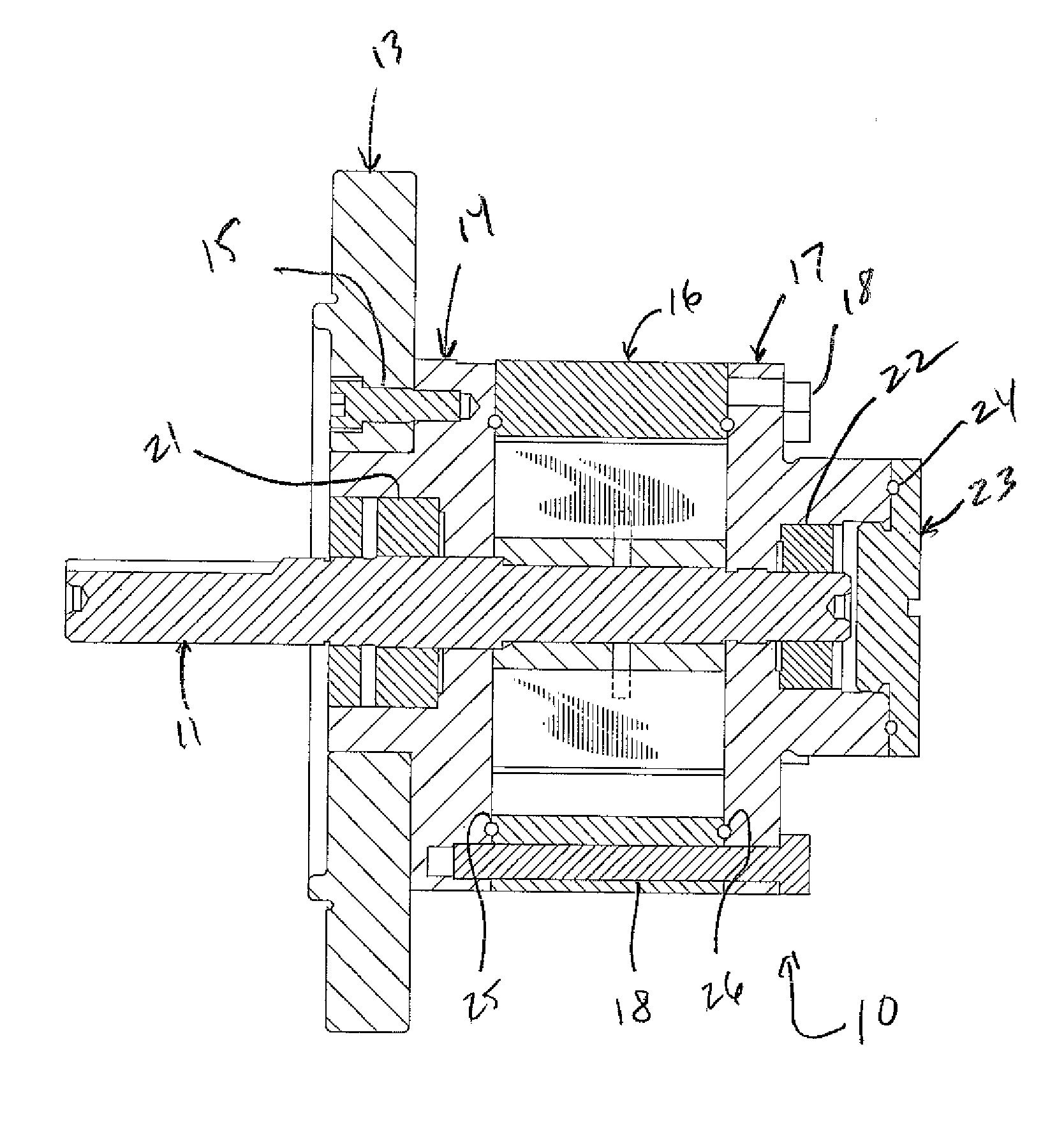
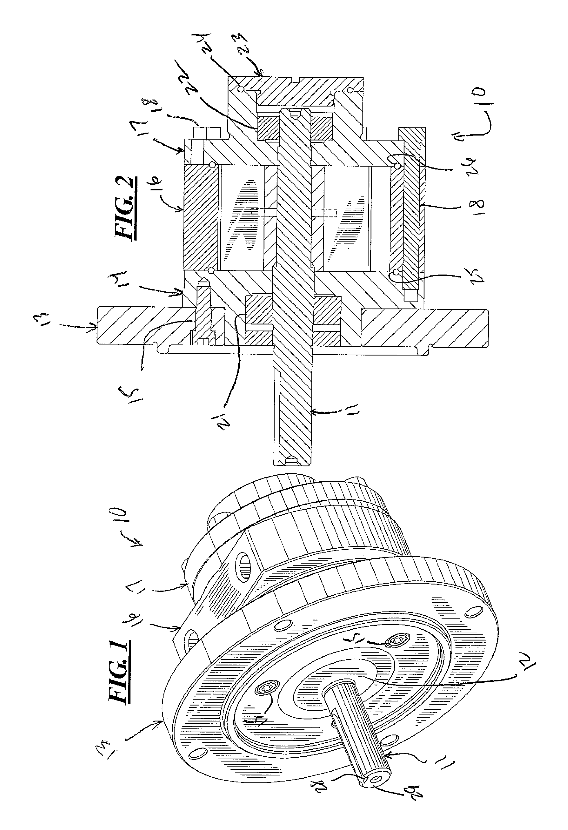
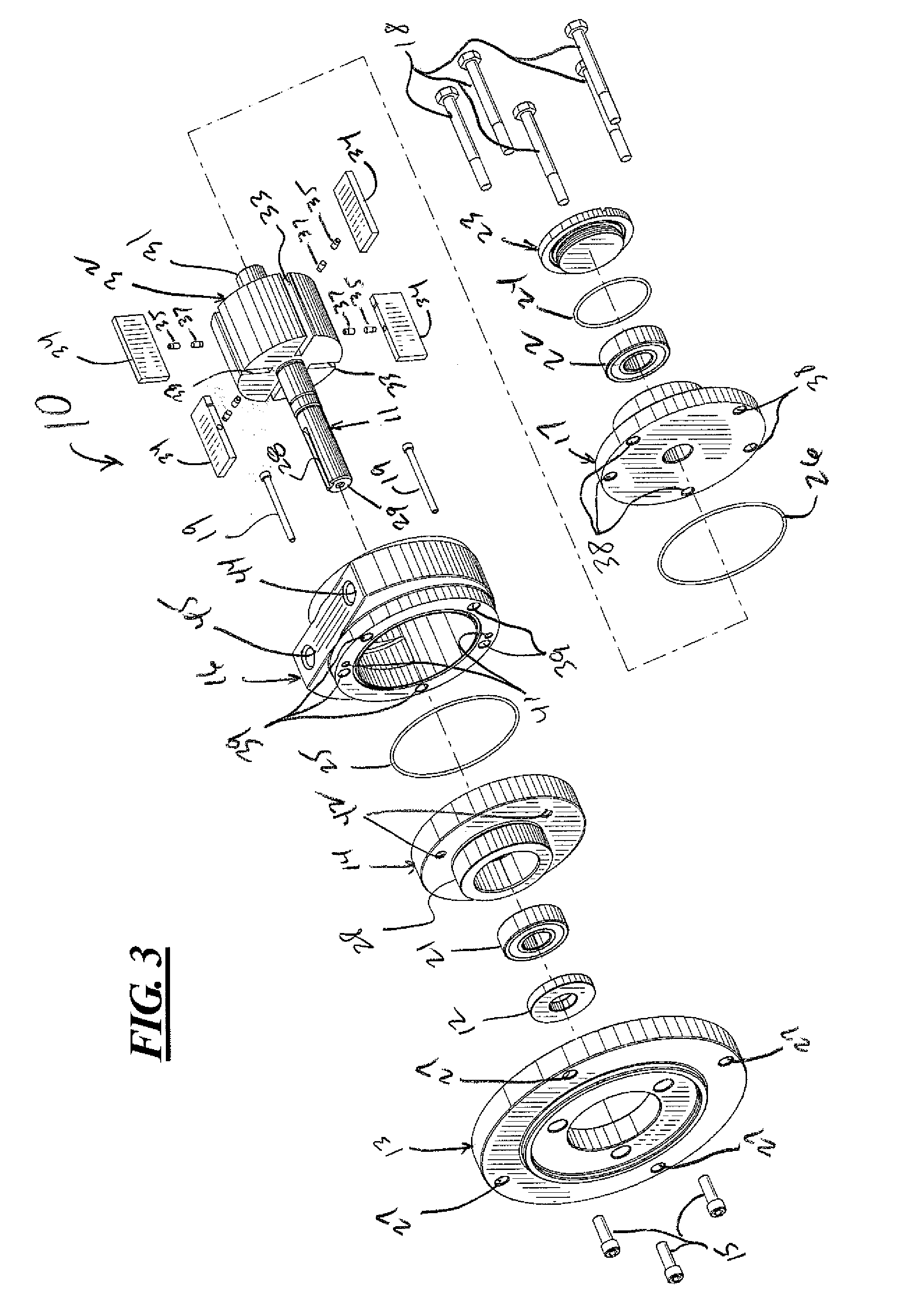
[0025]Turning first to FIG. 1, a pump 10 made in accordance with this disclosure is shown in a perspective view. The pump 10 includes a rotor shaft 11 that passes through a seal 12 and mounting bracket 13. The mounting bracket 13 is connected to a front plate 14 by a plurality of fasteners 15 as shown in FIGS. 1-2. A rotor casing 16 is sandwiched between the front plate 14 and a rear plate 17 as best seen in FIG. 2. The rear plate 17, casing 16 and front plate 14 are held together by a plurality of fasteners, two of which are shown at 18 in FIG. 2, while three others are shown in FIG. 3.

[0026]As shown in FIG. 3, fasteners 19 may be used to secure the casing 16 to the front plate 14. Referring to FIGS. 1-3, the rotor shaft 11 is supported by a front bearing 21 and a rear bearing 22. An end cap 23 and O-ring seat 24 seals the rear end of the pump 10 while the rotor seal 12 seals the front end of the pump 10. O-rings 25, 26 prevent fluid from leaking between the casing 16 and front and...


PUM

PropertyMeasurementUnit
polarityaaaaaaaaaa
polaritiesaaaaaaaaaa
magnetic forcesaaaaaaaaaa

Abstract

A magnetic rotary vane pump is disclosed which includes a rotor disposed within a casing that comprises a cavity having an inlet and an outlet. The rotor includes at least one radial slot and at least one vane carried by the radial slot. The vane includes an inner edge directed towards a central axis of the rotor and an outer edge directed towards the casing. The inner edge of the vane is connected to a first magnet. The slot in the rotor includes an inner wall that abuttingly engages or faces the inner edge of the vane when the vane is fully received within the slot. The inner wall of the slot is connected to a second magnet. The two magnets are arranged so that like pole of the magnets face each other thereby biasing the vane out of the slot and against the inner wall of the casing as the rotor rotates. Accordingly, no spring or pin is required to bias the vane outward against the casing or into recesses or slots disposed in the casing wall. The resulting design may be operated faster than conventional vane pumps and with less lubrication or no lubrication than conventional vane pumps.

Description

FIELD OF THE DISCLOSURE [0001]This disclosure relates to improved rotary vane pumps and, more specifically, to improved vane pump designs. Still more specifically, a rotary vane pump is disclosed wherein the vanes are biased away from the rotor and towards the inner wall of the casing by two magnets with opposite polarity, one magnet is disposed on an inner edge of the vane and the other disposed in the rotor body. The disclosed magnetic rotary vane pump designs are particularly useful in air motors but may be used in other applications where magnetic rotary vane pumps are employed.BACKGROUND OF THE DISCLOSURE [0002]Rotary vane pumps are positive-displacement pumps that consist of vanes mounted to a rotor that rotates inside of a cavity. In some cases, the vanes can vary in length or the outward force applied to the vanes can be varied to maintain good contact with the inside surface of the casing as the rotor of the pump rotates. The most simple vane pump is a circular rotor rotati...

Claims


Application Information

Patent Timeline
Patent Type & Authority Applications(United States)
IPC IPC(8): F04C29/00F04C2/04F04B17/00B23P15/00
CPCF01C21/0818Y10T29/49245F04C2/3442
Inventor YOUKER, CALEBJAQUES, CHRISTOPHER J.
Owner GAST MFG
Why Eureka
Try Eureka