
Automatic load transfer device and method for automated material handling systems

a technology of automatic load transfer and material handling system, which is applied in the direction of process and machine control, transportation items, instruments, etc., can solve the problems of unit load agv and fork agv, which are relatively expensive, and achieve the effects of high uptime reliability, efficient and reliable load transportation, and substantial reliability

Inactive Publication Date: 2009-10-08
SAVANT AUTOMATION
View PDF30 Cites 22 Cited by
  • Summary
  • Abstract
  • Description
  • Claims
  • Application Information

AI Technical Summary

Benefits of technology

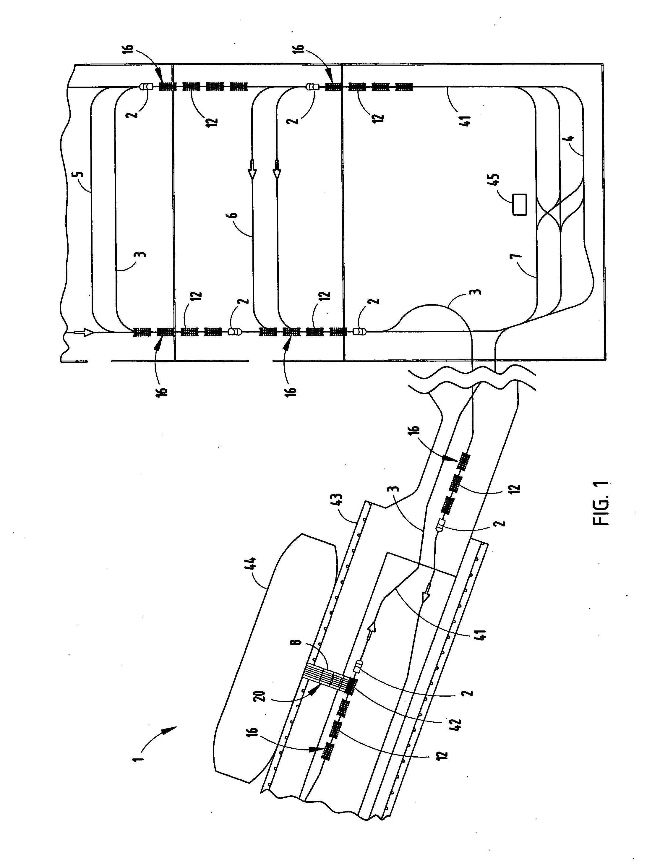
[0008]Yet another aspect of the present invention is an automated material handling system which is economical, and can efficiently and reliably transport loads between various stations even in challenging environments, such as heavy manufacturing and industrial plants, outside warehouse transports and the like. The use of a tow or tugger AGV in conjunction with non-powered, dumb trailers and a stationary, fully automated loader / unloader provides substantial reliability, economy and maintenance benefits. The automated material handling system has high uptime reliability, durability, and is capable of moving even heavy loads quickly over a wide variety of floor surfaces without damage to fragile loads. The automated material handling system has an uncomplicated construction, and can be readily expanded or reconfigured to accommodate a wide variety of different applications. The material handling system is efficient in use, economical to manufacture, capable of a long operating life, and particularly well adapted for the proposed use.

Problems solved by technology

In general, unit load AGVs and fork AGVs are relatively expensive, at least for many applications, since they include both sophisticated guidance systems, and some form of integrated loading and / or unloading mechanism.

Method used


Image

  • Automatic load transfer device and method for automated material handling systems
  • Automatic load transfer device and method for automated material handling systems
  • Automatic load transfer device and method for automated material handling systems

Examples


Embodiment Construction

[0053]For purposes of description herein, the terms “upper”, “lower”, “right”, “left”, “rear”, “front”, “vertical”, “horizontal” and derivatives thereof shall relate to the invention as oriented in an installed condition, as shown in FIGS. 1 and 34-43. However, it is to be understood that the invention may assume various alternative orientations and step sequences, except where expressly specified to the contrary. It is also to be understood that the specific devices and processes illustrated in the attached drawings, and described in the following specification, are simply exemplary embodiments of the inventive concepts defined in the appended claims. Hence, specific dimensions and other physical characteristics relating to the embodiments disclosed herein are not to be considered as limiting, unless the claims expressly state otherwise.

[0054]The reference numeral 1 (FIG. 1) generally designates a material handling system embodying the present invention, which in the example illust...


PUM


Abstract

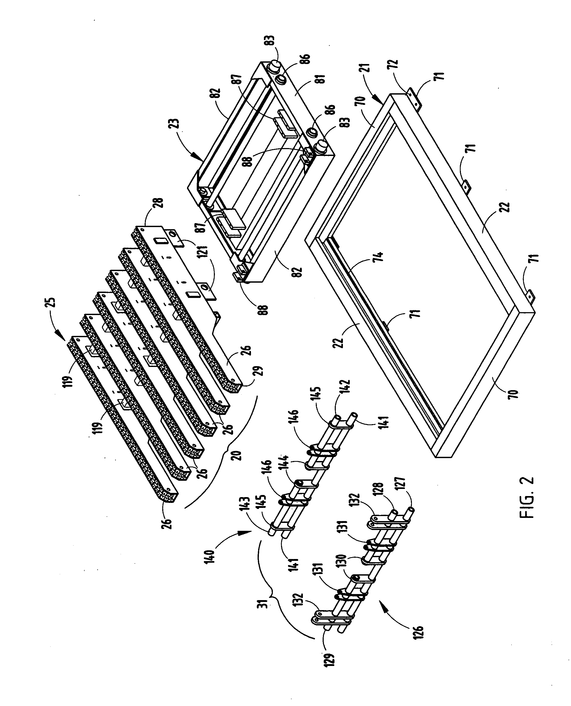
An automatic load transfer device is provided for automated material handling systems of the type having a tow AGV pulling a train of trailers along a predetermined path between stations. The device has a base positioned adjacent to the path with spaced apart rails that support a movable carriage which shifts between retracted and extended positions. A conveyor having a plurality of side-by-side fingers with moving conveyor elements is supported on the carriage by a lift which shifts the conveyor between lowered and raised positions. The carriage, conveyor elements, and lift have separate drives that are operably connected with a controller which sequentially activates the same to load and / or unload loads onto and / or from the trailers.

Description

BACKGROUND OF THE INVENTION[0001]The present invention relates to automated material handling systems, as well as an automatic load transfer device therefor.[0002]Automatic guided vehicles (“AGV”s) are well known in the art, and are used in numerous automated material handling systems to move loads of raw materials, manufactured parts and / or other commodities between various stations. AGVs are typically grouped into four different types, including unit load AGVs, cart AGVs, fork AGVs and tow AGVs. Tow AGVs have sophisticated guidance systems, and are configured to pull conventional non-powered trailers arranged in a train. Unit load AGVs also have sophisticated guidance systems, and incorporate a mechanism to load and / or unload the same. Cart AGVs also have guidance systems, and are designed to place loads directly on top of the same, while fork lift AGVs are designed to lift palletized loads and deposit the same at a desired location. In general, unit load AGVs and fork AGVs are re...

Claims


Application Information

Patent Timeline
Patent Type & Authority Applications(United States)
IPC IPC(8): B60P1/00
CPCB60L15/38B60L2200/44B60L2260/32B65G63/022B60L2200/26G05D1/0225G05D1/0263G05D2201/0205G05D2201/0216B66F9/063Y02P90/60
Inventor TUFFS, MONTE R.KOFF, GARRY A.REDMANN, JR., JERRY L.
Owner SAVANT AUTOMATION
Learn More