Phase coupler for rotating fields

Active Publication Date: 2009-10-22
CHECKPOINT SYST INC
View PDF36 Cites 13 Cited by
  • Summary
  • Abstract
  • Description
  • Claims
  • Application Information

AI Technical Summary

Benefits of technology

[0026]It is the object of this invention to eliminate the analog phase-shifting circuit for both transmission and receiving, thus eliminating the insertion loss and

Problems solved by technology

However, a detection null is created in the area near the intersection of the figure eight crossover due to the magnetic field lines running in parallel to the plane of the tag.
This causes significantly reduced detection as optimal detection is achieved when the magnetic field lines run perpendicular to the plane of the tag.
A single antenna loop element inevitably generates an uneven interrogation zone with respect to tag position and orientation.
Synchronous demodulation, or phase-sensitive detection, will not work well with a rotating field that in effect constantly rotates the tag.
A practical issue with the phase-shift by means of mutual coupling is that it

Method used


Image

  • Phase coupler for rotating fields
  • Phase coupler for rotating fields
  • Phase coupler for rotating fields

Examples


Embodiment Construction

[0065]This invention 20 (see FIG. 9A) relates to dynamically controlled electronic article surveillance (EAS) systems whereby an array of antenna elements (Ant. 1, Ant. 2, . . . Ant. K) is digitally phased and actively driven for concurrent transmission 22 and digitally phased and then combined in the receiver unit 24 to improve detection of a security tag 10. All of this is arranged from a central coordination 26 (e.g., processor). In particular, the transmit and receive interrogating field is digitally scanned such that detection may be reinforced in some desired locations and still be insensitive to tag orientation suppressed in some other locations. In one manifestation of the invention, active phasing of multiple antenna elements for concurrent transmission is performed digitally using a direct digital synthesizer (DDS).

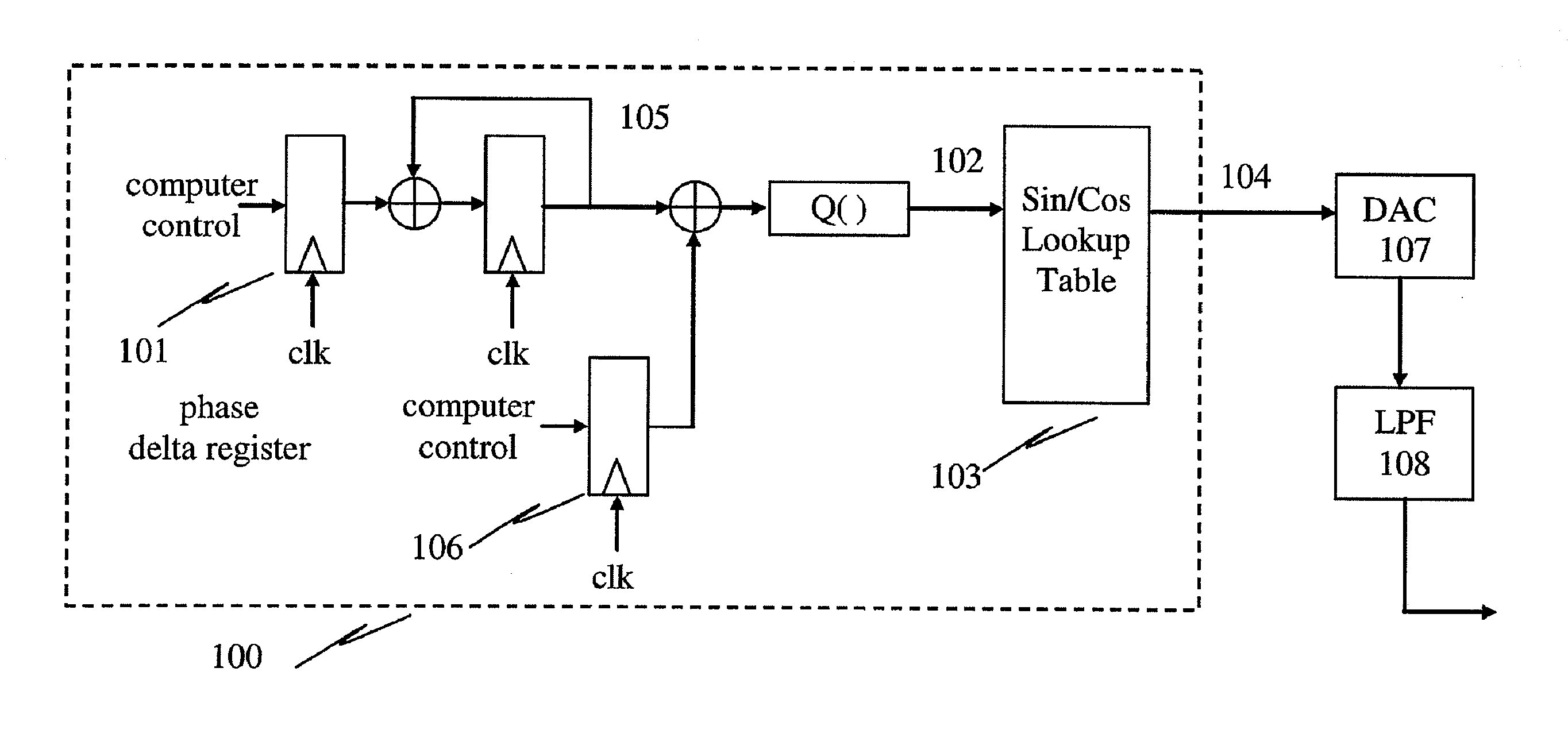
[0066]FIG. 10 shows a high-level view of the DDS 100. A phase delta 101 controlling the output frequency is accumulated (i.e., digitally-integrated in time) and...


PUM


Abstract

This invention relates to dynamically controlled, electronic article surveillance (EAS) systems whereby an array of antenna elements is digitally phased and actively driven for concurrent transmission, and digitally phased and combined in the receiver unit to improve detection. In particular, the individual frequency and phase of the plurality of the transmit/receive signals are rapidly varied to allow for automated manipulation (steering) of the transmit field pattern and receive field sensitivity. The invention achieves the following features via means of digital phasing and dynamic computer control: sufficient far-field cancellation, null-free detection and uncompromised detection performance regardless of tag's orientation while using single transmission drivers to drive entire antenna structures, whether loop antenna or ferrite core antenna, using a phase coupler, thereby allowing more efficient system operation or additional features such as deactivator antenna operation.

Description

CROSS-REFERENCE TO RELATED APPLICATIONS[0001]This Continuation-in-Part application claims the benefit under 35 U.S.C. §120 of application Ser. No. 12 / 134,827 filed on Jun. 6, 2008 entitled DYNAMIC EAS DETECTION SYSTEM AND METHOD which in turn claims the benefit under 35 U.S.C. §119(e) of Provisional Application Ser. No. 60 / 942,873 filed on Jun. 8, 2007 entitled DYNAMIC EAS DETECTION and all of whose entire disclosures are incorporated by reference herein.BACKGROUND OF THE INVENTION[0002]1. Field of Invention[0003]This invention relates to dynamically controlled, digitally-phased, multiple antenna elements for generating a dynamically enhanced electromagnetic field for orientation-independent tag detection and digital synthesis techniques which improves signal sensitivity of electronic article surveillance (EAS) systems.[0004]2. Description of Related Art[0005]An electronic article surveillance (EAS) system typically consists of (a) tags, (b) interrogation antenna(s), and (c) interro...

Claims


Application Information

Patent Timeline
IPC IPC(8): G08B13/22
CPCG08B13/2471G08B13/2474G08B13/2477H01Q7/06H01Q3/26H01Q7/00H01Q1/2216
Inventor OUNG, HARRYZENG, KEFENG
Owner CHECKPOINT SYST INC
Why Eureka
Try Eureka