
A phase shifter and antenna

A phase shifter and antenna technology, applied in the field of communication, can solve problems such as reducing antenna performance, achieve the effect of eliminating insertion loss and improving phase shifting performance

Active Publication Date: 2022-06-24
SHANGHAI TIANMA MICRO ELECTRONICS CO LTD
View PDF13 Cites 0 Cited by
  • Summary
  • Abstract
  • Description
  • Claims
  • Application Information

AI Technical Summary

Problems solved by technology

[0003] In the existing liquid crystal antenna, the microstrip line is used as the liquid crystal deflection electrode to drive the deflection of the liquid crystal molecules. There is an isolation gap structure between the feed network and the microstrip line, and the radio frequency signal on the feed network is transmitted to the microstrip line through coupling. To prevent crosstalk between the driving voltages on the microstrip lines in different phase shifters, but the isolation slot structure will introduce additional insertion loss and reduce the performance of the antenna

Method used


Image

  • A phase shifter and antenna
  • A phase shifter and antenna
  • A phase shifter and antenna

Examples


Embodiment Construction

[0025] The present invention will be further described in detail below in conjunction with the accompanying drawings and embodiments. It should be understood that the specific embodiments described herein are only used to explain the present invention, but not to limit the present invention. In addition, it should be noted that, for the convenience of description, the drawings only show some but not all structures related to the present invention.

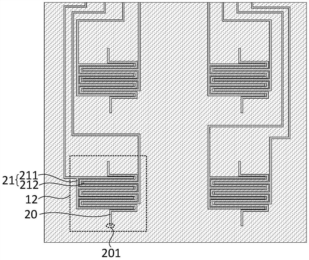
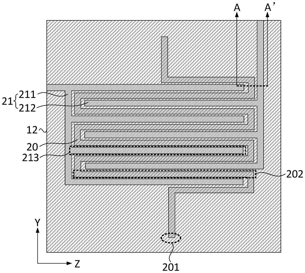
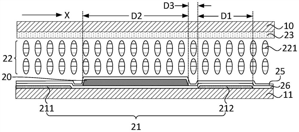
[0026] figure 1 A schematic structural diagram of a phase shifter provided by an embodiment of the present invention, figure 2 A schematic structural diagram of a phase shifting unit provided in an embodiment of the present invention, image 3 for figure 2 A schematic diagram of the cross-sectional structure along the A-A' direction, such as Figure 1-3 As shown, the phase shifter provided by the embodiment of the present invention includes a first substrate 10, a second substrate 11 and at least one phase shifting unit 12 ar...


PUM


Abstract

The invention discloses a phase shifter and an antenna. Wherein, the phase shifter includes a first substrate and a second substrate oppositely arranged and at least one phase shifting unit, the phase shifting unit includes a microstrip line, a driving electrode, a liquid crystal layer and a first metal layer, and the microstrip line is located near the second substrate On one side of the first substrate, the first metal layer is located on the side of the first substrate close to the second substrate, the liquid crystal layer is located between the first substrate and the second substrate; the driving electrode is located on the side of the liquid crystal layer away from the first substrate, and the driving The electrodes are used to drive liquid crystal molecules in the liquid crystal layer to deflect, and the microstrip line includes a radio frequency signal receiving end for receiving radio frequency signals. The phase shifter and the antenna provided by the embodiment of the present invention separate the drive electrode for driving the deflection of the liquid crystal molecules and the microstrip line for transmitting the radio frequency signal, so that there is no need to set an isolation gap structure between the microstrip line and the radio frequency signal transmission line, thereby reducing the The insertion loss is reduced, and the phase shift performance of the phase shifter is improved.

Description

technical field [0001] Embodiments of the present invention relate to the field of communications technologies, and in particular, to a phase shifter and an antenna. Background technique [0002] Liquid crystal antenna is a new type of reconfigurable antenna system that combines traditional microstrip patch antenna and liquid crystal material. It combines liquid crystal and microstrip line to adjust the arrangement of liquid crystal, thereby realizing the adjustment of relative permittivity of liquid crystal. A liquid crystal phase shifter is formed, and the liquid crystal phase shifter is combined with a patch radiator to form a liquid crystal antenna structure that can perform electrical scanning. [0003] In the existing liquid crystal antenna, the microstrip line is used as the liquid crystal deflection electrode to drive the deflection of the liquid crystal molecules. There is an isolation gap structure between the feeding network and the microstrip line. The radio freq...

Claims


Application Information

Patent Timeline
Patent Type & Authority Patents(China)
IPC IPC(8): H01P1/18H01Q3/34
CPCH01P1/18H01Q3/34
Inventor 贾振宇席克瑞刘桢林柏全秦锋
Owner SHANGHAI TIANMA MICRO ELECTRONICS CO LTD
Learn More