Fluorescent lamp driver circuit

Inactive Publication Date: 2009-10-29
NIKO SEMICON
View PDF4 Cites 4 Cited by
  • Summary
  • Abstract
  • Description
  • Claims
  • Application Information

AI Technical Summary

Benefits of technology

[0008]It is an object of the present invention to further reduce the number of pins and the number of required electronic components of a multi-lamp driver circuit, so as to lower the cost of the circuit and simplify the circuit layout. The present invention provides a fluorescent lamp driver circuit comprising a switch module, a resonance module, a first fluorescent lamp module, a second fluorescent lamp module, a detection unit, a selection unit, a protection unit, and a control unit. The switch module is coupled to a DC input voltage and controls the magnitude of an output electric power according to a plurality of control signals. The resonance module is coupled to the switch module for converting the output electric power into a first AC signal and a second AC signal, wherein the first AC signal and the second AC signal are almost in opposite phases. In other words, the phase difference between the first AC signal and the second AC signal falls within a predetermined range from 180 degrees. The first fluorescent lamp module is coupled to the resonance module for receiving the first AC signal, and the second fluorescent lamp module is coupled to the resonance module for receiving the second AC signal. The detection unit includes a first detecting portion and a second detecting portion. One end of the first detecting portion and one end of the second detecting portion are coupled with a common ground. The other end of the first detecting portion is serially connected to the first fluorescent lamp module for generating a first detection signal, and the other end of the second detecting portion is serially connected to the second fluorescent lamp module for generating a second detection signal. The selection unit receives the first detection signal and the second detection signal and outputs a select signal. The protection unit receives the first detection signal and the second detection signal and outputs a protection feedback signal. The control unit is coupled to the selection unit and the protection unit, and generates the plurality of control signals according to the select signal for controlling the switching of the switch module. The control unit stops the switching of the switch module if the level of the protection feedback signal is higher than a predetermined value.
[0011]In summation of the description above, the fluorescent lamp driver circuit provided in the present invention can achieve the object of feedback control of multi-lamp and circuit protection by using the detection signal selected by the selection unit, and even adjust and control the level of the output detection signal according to the protection feedback signal to achieve the object of using a single feedback signal to provide the functions of the feedback control and circuit protection. The present invention can also simplify the circuit design and reduce the number of electronic components significantly.

Problems solved by technology

The traditional circuit design with single PWM controller and single resonance module to drive single lamp may incur complicated circuits and high costs of such backlight device.

Method used


Image

  • Fluorescent lamp driver circuit
  • Fluorescent lamp driver circuit
  • Fluorescent lamp driver circuit

Examples


Embodiment Construction

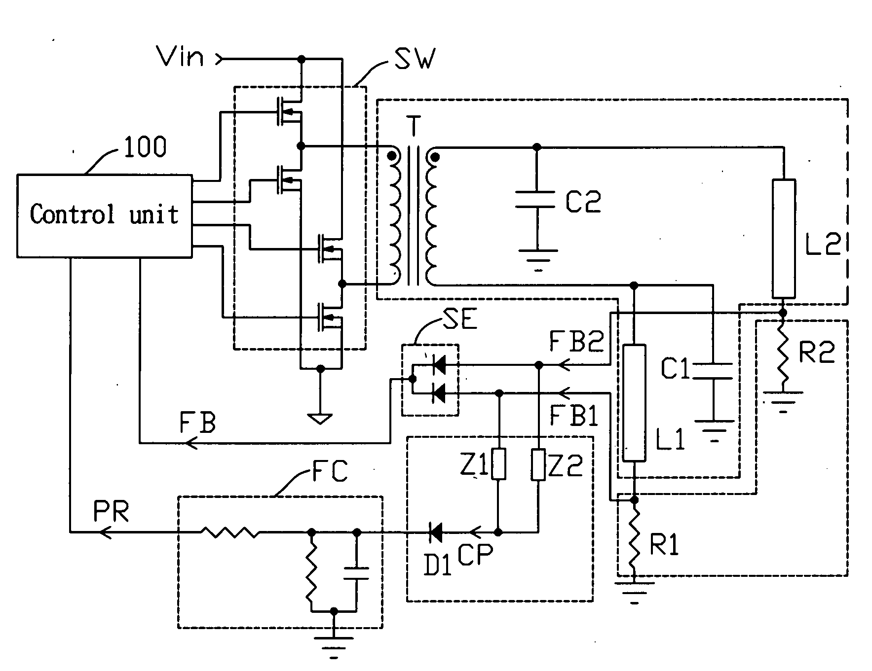
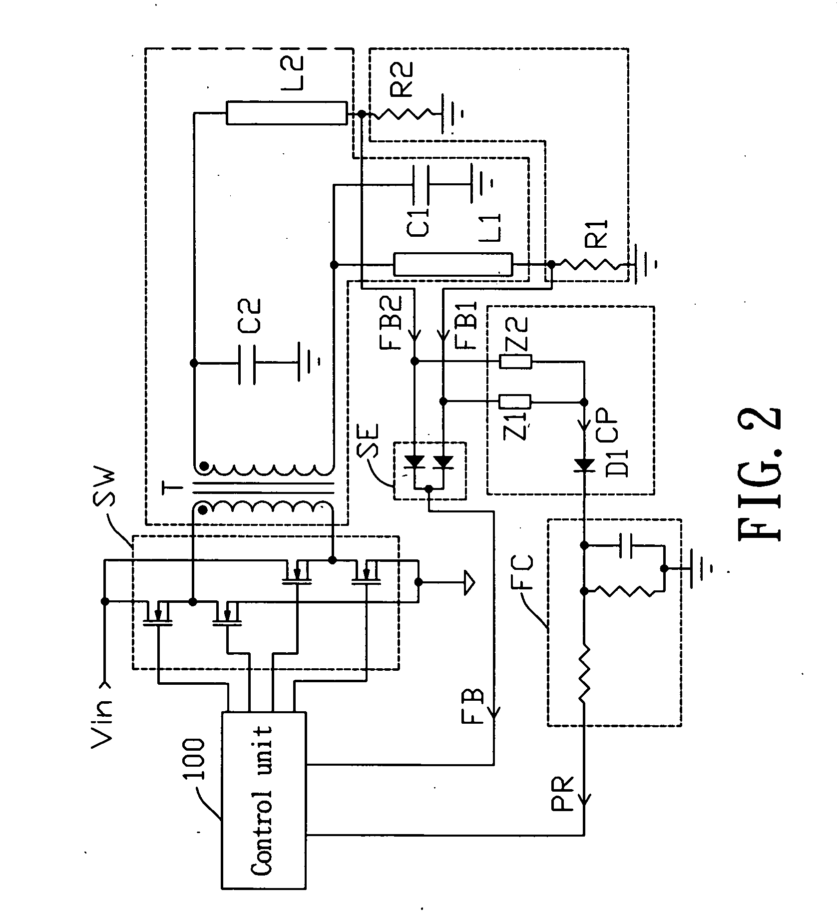
[0020]With reference to FIG. 2 for a circuit diagram of a multi-lamp driver circuit in accordance with a first preferred embodiment of the present invention, the multi-lamp driver circuit comprises a switch module SW, a resonance module, a first fluorescent lamp module L1, a second fluorescent lamp module L2, a detection unit, a protection unit, and a control unit 100. The switch module SW is coupled to a DC input voltage Vin and is switched according to a control signal from the control unit 100 so as to control the magnitude of the output electric power. The switch module SW of this embodiment has a full-bridge architecture, but in practical, a half-bridge architecture or a push-pull architecture can be adopted in the switch module SW as well. The resonance module comprises resonant capacitors C1, C2 and a transformer T with a primary side and a secondary side. The primary side of the transformer T is coupled to the switch module SW, and the secondary side of the transformer T is ...


PUM


Abstract

A fluorescent lamp driver circuit is provided. The fluorescent lamp driver circuit uses reversed current detecting signal to achieve feedback control and circuit protection so as to simplify the driver circuit and reduces the number of the required electronic components. The driver circuit needs a single control unit to control the whole circuit, which not only reduces cost, but also simplifies circuit design.

Description

BACKGROUND OF THE INVENTION[0001]1. Field of the Invention[0002]The present invention relates to a fluorescent lamp driver circuit, and more particularly to a multi-lamp cold cathode fluorescent lamp (CCFL) driver circuit.[0003]2. Description of Related Art[0004]In a backlight device of a liquid crystal display (LCD), a high-frequency sine wave AC power supply is usually adopted for supplying electric power to drive a cold cathode fluorescent lamp (CCFL) to emit light. Therefore, a DC / AC inverter circuit is demanded for converting energy. The typical CCFL driver circuit usually has a resonance module to convert a DC voltage into an AC voltage for driving the CCFL to emit light. Voltage and current detect circuits are usually used for detecting a driving voltage and a driving current of the CCFL, respectively. A pulse width modulation (PWM) controller receives a voltage detection signal and a current detection signal for stabilizing the illumination of the CCFL and for circuit protec...

Claims


Application Information

Patent Timeline
IPC IPC(8): H05B41/36
CPCH05B41/2855
Inventor WANG, CHEN-HSUNGCHANG, SHU-MING
Owner NIKO SEMICON
Why Eureka
Try Eureka