

Low Oil Trip Assembly for a Fault Interrupter and Load Break Switch
a load break switch and low oil trip technology, which is applied in the direction of circuit breakers, machines/engines, instruments, etc., can solve the problems of increasing the cost of acquiring and maintaining the transformer, the failure to protect the primary circuit circuit circuit breaker, and the length and complexity of the safety practices for determining if the fuse is damaged and replacing the fuse, etc., to achieve the effect of increasing the voltage capacity of the switch
- Summary
- Abstract
- Description
- Claims
- Application Information
AI Technical Summary
Benefits of technology
Problems solved by technology
Method used
Image

Examples
Embodiment Construction
[0046]The following description of exemplary embodiments of the invention refers to the attached drawings, in which like numerals indicate like elements throughout the several figures.
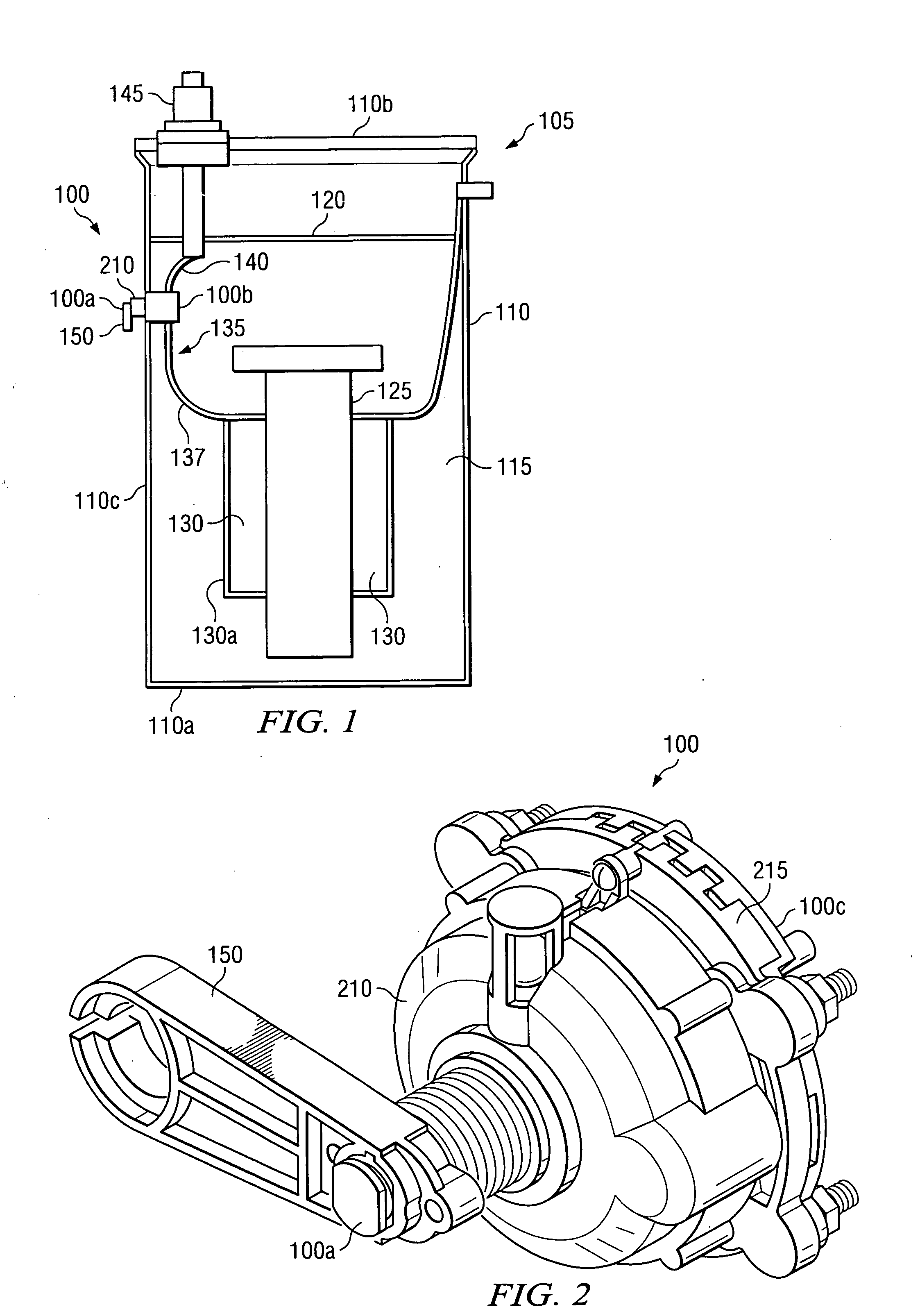
[0047]FIG. 1 is a cross-sectional perspective view of an exemplary fault interrupter and load break switch 100 mounted to a tank wall 110c of a transformer 105, in accordance with certain exemplary embodiments. The transformer 105 includes a tank 110 that is at least partially filled with a dielectric fluid 115. The dielectric 115 fluid includes any fluid that can act as an electrical insulator. For example, the dielectric fluid can include mineral oil. The dielectric fluid 115 extends from a bottom 110a of the tank 110 to a height 120 proximate a top 110b of the tank 110. The dielectric fluid 115 surrounds a core 125 and windings 130 of the transformer 105.
[0048]The switch 100 is electrically coupled to a primary circuit 135 of the transformer 105 via wires 137 and 140. Wire 137 extends between the sw...
PUM
 Abstract
Description
Claims
Application Information