
Multiple Arc Chamber Assemblies for a Fault Interrupter and Load Break Switch

a load break switch and fault interrupter technology, applied in circuit-breaking switches, contact mechanisms, waveguide types, etc., can solve the problems of increasing the cost of acquiring and maintaining transformers, affecting and affecting the safety of transformers. , to achieve the effect of increasing the voltage capacity of switches

Active Publication Date: 2009-11-12
EATON INTELLIGENT POWER LTD
View PDF10 Cites 9 Cited by
  • Summary
  • Abstract
  • Description
  • Claims
  • Application Information

AI Technical Summary

Benefits of technology

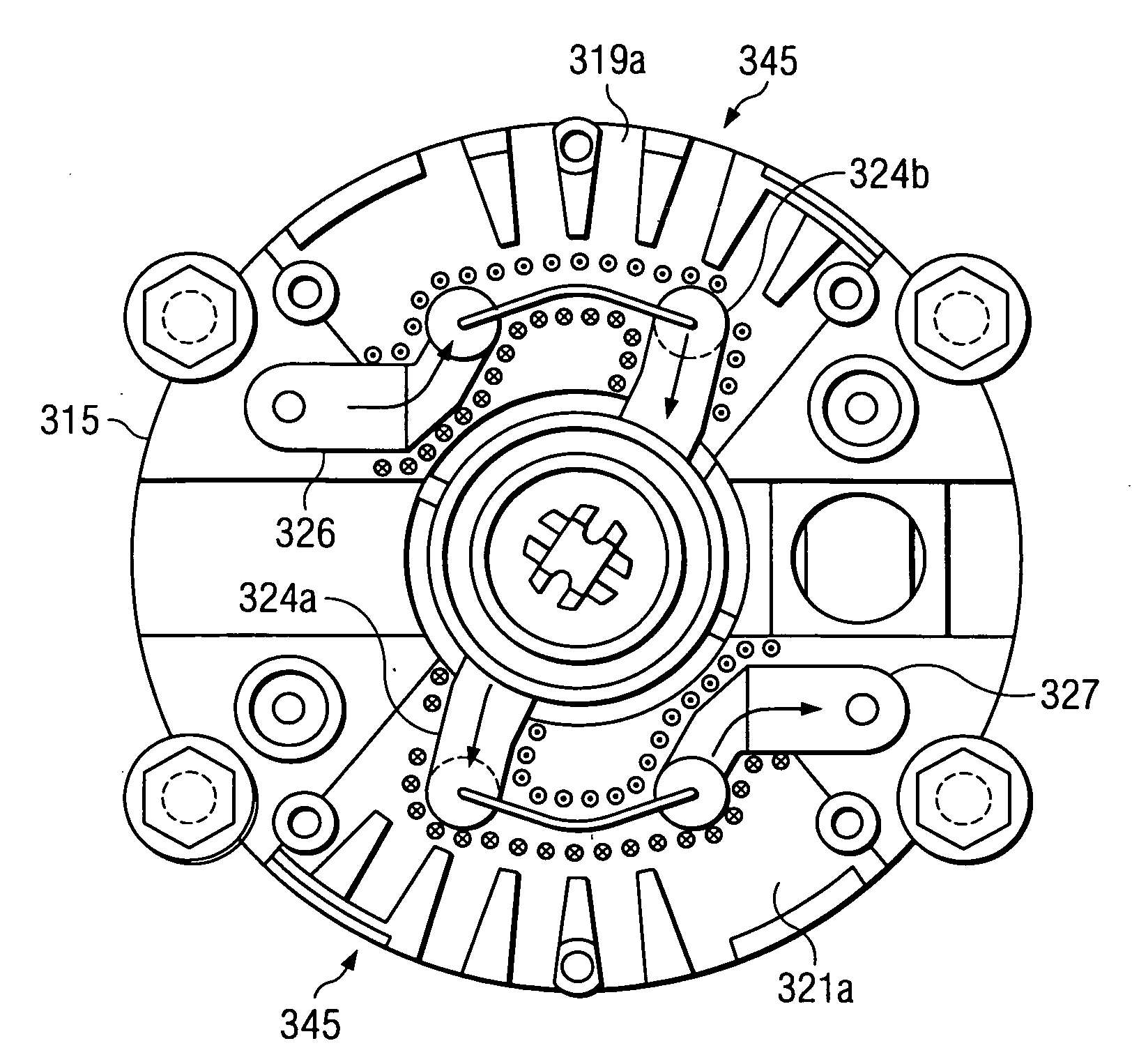
[0016]The electrical circuit is opened in two places—a junction between a first pair of the movable contact ends and stationary contacts and a junction between a second pair of the movable contact ends and stationary contacts. This “double break” of the circuit increases a total arc length of an electric arc generated during the circuit opening. This increased arc length increases the arc's voltage, making the arc easier to extinguish. The increased arc length also helps to prevent arc re-initiation, also called “restrikes.”
[0017]Vents within the arc chamber assembly are configured to allow ingress and egress of dielectric fluid for extinguishing the arc. Internally, arc chamber walls leading to the vents can be designed in smooth up and down transitions and without perpendicular walls or other obstructions to the flow of dielectric fluid and arc gasses. Obstructions could cause turbulence in the flow of fluid and gas during circuit opening. Obstructions to flow and turbulence could in turn prevent the arc from being moved to the location within the arc chamber, at the proper time, that is best suited for extinguishing the arc. The vents also are sized and shaped to prevent the arc from traveling outside the arc chamber assembly and striking the tank wall or other internal transformer components.
[0018]In certain alternative exemplary embodiments, a solenoid can be used instead of the Curie metal element, magnet, and spring to actuate the rocker. Other alternatives include a bimetal element and a shape memory metal element. The solenoid can be operated through electronic controls. The electronic controls may provide greater flexibility in selecting trip parameters such as trip times, trip currents, trip temperatures, and reset times. The electronic controls also may allow for switch operation via remote wireless or hard wired means of communications.
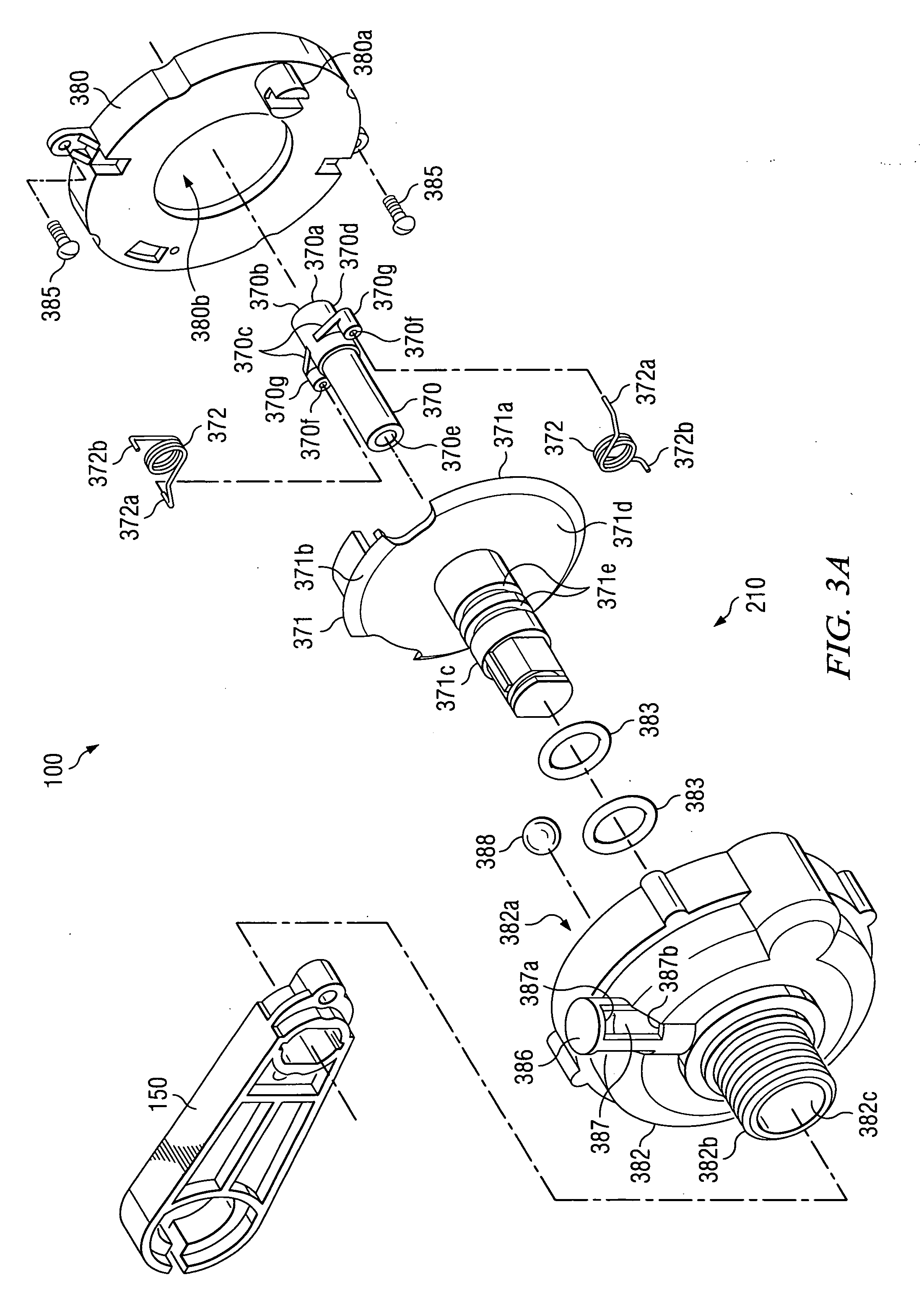
[0019]In a manual operation of the switch, actuation of a handle coupled to the rotor assembly via a spring-loaded rotor causes the movable contact ends to selectively engage or disengage the stationary contacts. The primary function of the spring-loaded rotor is to minimize arcing between the stationary contacts and the ends of the movable contact in the arc chamber assembly by very rapidly driving the contacts into their open or closed positions. Thus, rotor rotational speed can be consistent, independent of handle speed, which may be under inconsistent operator control.
[0022]The arc chamber assemblies may be connected in series or in parallel. An in-parallel connection allows a single switch to control multiple different circuits. An in-series connection increases the voltage capacity of the switch. For example, if a single arc chamber assembly can interrupt 8,000 volts at 3,000 amps AC, then a combination of three arc chamber assemblies may interrupt 24,000 volts at 3,000 amps AC.

Problems solved by technology

Methods and safety practices for determining if the fuse is damaged and for replacing the fuse can be lengthy and complicated.
The circuit breaker does not protect against faults in the primary circuit.
As the size of the transformer tank increases, the cost of acquiring and maintaining the transformer increases.
The large size of the load break switch and the extra device employed for fault protection require a much larger, and more expensive, transformer tank.

Method used


Image

  • Multiple Arc Chamber Assemblies for a Fault Interrupter and Load Break Switch
  • Multiple Arc Chamber Assemblies for a Fault Interrupter and Load Break Switch
  • Multiple Arc Chamber Assemblies for a Fault Interrupter and Load Break Switch

Examples


Embodiment Construction

[0046]The following description of exemplary embodiments of the invention refers to the attached drawings, in which like numerals indicate like elements throughout the several figures.

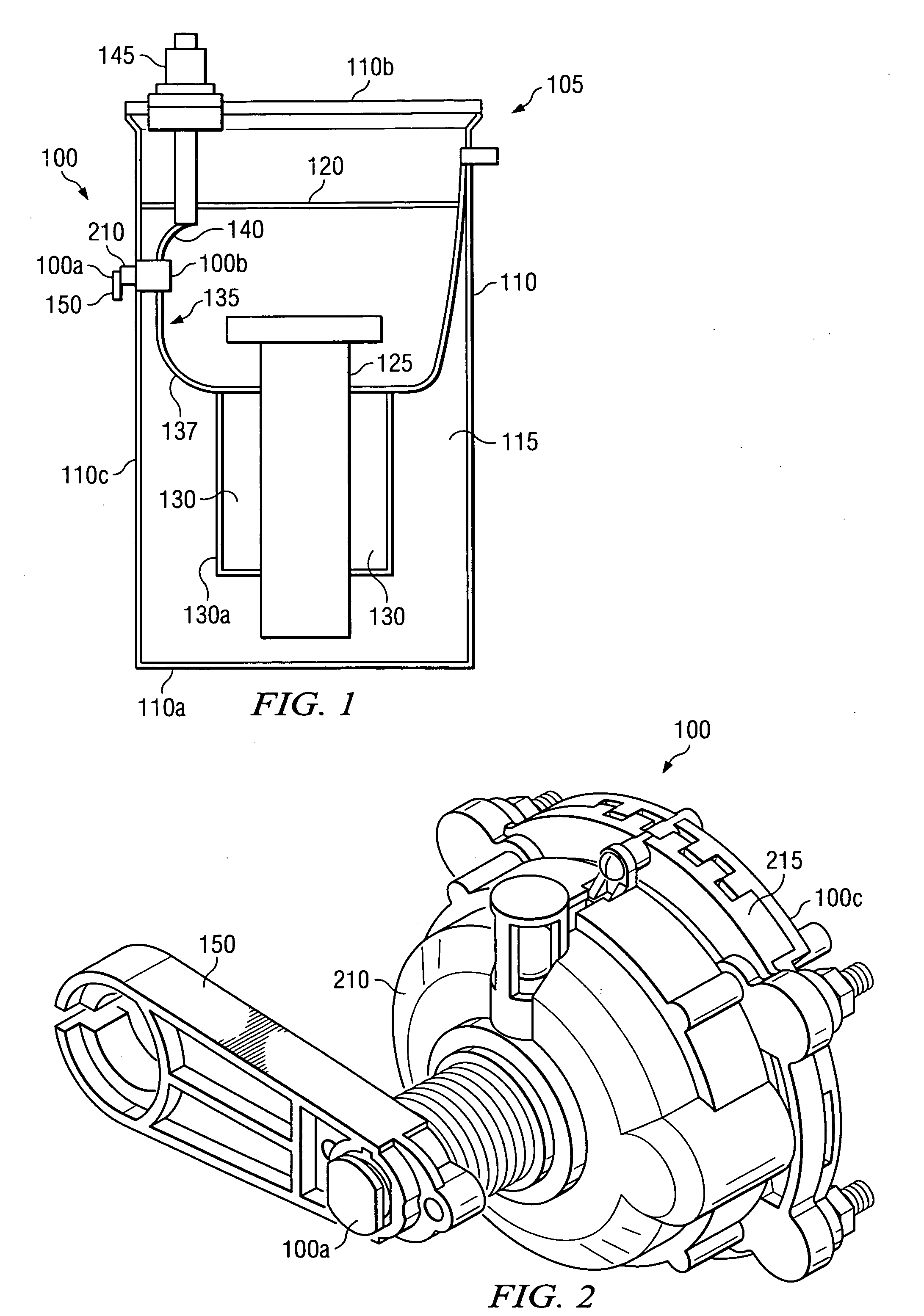
[0047]FIG. 1 is a cross-sectional perspective view of an exemplary fault interrupter and load break switch 100 mounted to a tank wall 110c of a transformer 105, in accordance with certain exemplary embodiments. The transformer 105 includes a tank 110 that is at least partially filled with a dielectric fluid 115. The dielectric 115 fluid includes any fluid that can act as an electrical insulator. For example, the dielectric fluid can include mineral oil. The dielectric fluid 115 extends from a bottom 110a of the tank 110 to a height 120 proximate a top 110b of the tank 110. The dielectric fluid 115 surrounds a core 125 and windings 130 of the transformer 105.

[0048]The switch 100 is electrically coupled to a primary circuit 135 of the transformer 105 via wires 137 and 140. Wire 137 extends between the sw...


PUM


Abstract

A fault interrupter and load break switch includes a trip assembly configured to automatically open a transformer circuit electrically coupled to stationary contacts of the switch upon the occurrence of a fault condition. The fault condition causes a Curie metal element electrically coupled to at least one of the stationary contacts to release a magnetic latch. The release causes a trip rotor of the trip assembly to rotate a rotor assembly. This rotation causes ends of a movable contact of the rotor assembly to electrically disengage the stationary contacts, thereby opening the circuit. The switch also includes a handle for manually opening and closing the electrical circuit in fault and non-fault conditions. Actuation of the handle coupled to the rotor assembly via a spring-loaded rotor causes the movable contact ends to selectively engage or disengage the stationary contacts.

Description

RELATED PATENT APPLICATION[0001]This patent application is related to co-pending U.S. patent application Ser. No. ______ [Attorney Docket No. 13682.105019 (RTC-027979)], entitled “Fault Interrupter and Load Break Switch,” filed ______; U.S. patent application Ser. No. ______ [Attorney Docket No. P06-028298], entitled “Low Oil Trip Assembly for a Fault Interrupter and Load Break Switch,” filed ______; U.S. patent application Ser. No. ______ [Attorney Docket No. P06-028292], entitled “Indicator for a Fault Interrupter and Load Break Switch,” filed ______; U.S. patent application Ser. No. ______ [Attorney Docket No. P06-028297], entitled “Adjustable Rating for a Fault Interrupter and Load Break Switch,” filed ______; and U.S. patent application Ser. No. ______ [Attorney Docket No. P06-028296], entitled “Sensor Element for a Fault Interrupter and Load Break Switch,” filed ______. The complete disclosure of each of the foregoing related applications is hereby fully incorporated herein by...

Claims


Application Information

Patent Timeline
Patent Type & Authority Applications(United States)
IPC IPC(8): H01H77/00H01H19/02
CPCH01H1/2041H01H9/34H01H9/342H01H73/045H01H71/142H01H71/56H01H37/58
Inventor LINDSEY, KURT LAWRENCEMALLIET, RANDAL VERNON
Owner EATON INTELLIGENT POWER LTD
Learn More