Switch device

A technology of switchgear and moving contact, which is applied in the direction of electric switch, electrical components, contact electrical connection, etc. It can solve the problems of large phase-to-phase distance, increased installation space of power distribution cabinet, and arc burnt contact surface, etc. , to achieve easy exhaust and heat dissipation, ensure effective work, and improve breaking capacity

Active Publication Date: 2019-04-05
SOOAR TIANJIN ELECTRICAL EQUIP CO LTD
View PDF6 Cites 4 Cited by
  • Summary
  • Abstract
  • Description
  • Claims
  • Application Information

AI Technical Summary

Problems solved by technology

[0006] 1. The existing isolating switch does not have a special arc extinguishing device, and cannot cut off the load current and short-circuit current. It is impossible to avoid the contact surface of the contact being ablated by the arc during use, and the contact quality cannot be guaranteed.
[0007] 2. Although some isolating switches are equipped with an arc extinguishing device, the arc extinguishing device is installed in the base of the isolating switch. This arrangement leads to a large distance between phases, which in turn leads to a large overall volume of the isolating switch. In addition, the isolating switch is in When connecting the molded case circuit breaker, it is necessary to transfer the busbar, and the corresponding installation space of the power distribution cabinet used together with it will also increase, causing inconvenience in installation and use
[0008] 3. The arc generated when the dynamic and static contacts of the isolating switch are separated will burn the surface of the contact, resulting in the failure of the isolating switch to work normally;
[0009] 4. There is still room for improvement in the short-time withstand current of the existing isolating switch

Method used


Image

  • Switch device
  • Switch device
  • Switch device

Examples


Embodiment Construction

[0051] The following will clearly and completely describe the technical solutions in the embodiments of the present invention with reference to the accompanying drawings in the embodiments of the present invention. Obviously, the described embodiments are only some, not all, embodiments of the present invention. Based on the embodiments of the present invention, all other embodiments obtained by persons of ordinary skill in the art without making creative efforts belong to the protection scope of the present invention.

[0052] The orientation terms such as "up", "down", "left" and "right" in the present invention are figure 1 The position shown in the

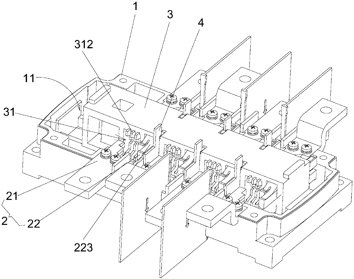
[0053] Such as figure 1 As shown, the present invention provides a switchgear 10, including an insulating housing 1 and at least one set of contact parts 2, wherein: an insulating beam 3 is movably arranged in the insulating housing 1, and at least An arc extinguishing structure 31; the contact part 2 includes a static conta...


PUM


Abstract

The invention provides a switch device. The switch device comprises an insulation housing which in movably and internally provided with an insulation beam, wherein the insulation beam is provided withat least one arc extinguishing structure; at least one set of contact portions, wherein each contact portion comprises a fixed contact and at least one moving contact which are in contact or separated from each other, the fixed contact is connected on the insulation housing, and the at least one moving contact is connected with the insulation beam. The switch device is provided with the at leastone arc extinguishing structure in the insulation beam so as to achieve a good arc extinguishing effect and effectively reduce the size of the switch device.

Description

technical field [0001] The invention relates to the technical field of low-voltage electrical appliances, in particular to a switchgear. Background technique [0002] At present, the requirements for miniaturization and high parameters of electrical products are gradually put forward in the market. Therefore, the isolating switch is required to be miniaturized and to meet the AC and DC switching and breaking capabilities, and to always meet the temperature rise requirements. At present, the common isolating switch and its contact system on the market use double breakpoints to make and break the current. In a limited space, it is difficult to extinguish the arc, so the contact surface of the contact will inevitably be burned, and even the product will be damaged. Unable to open and close normally and cause a short circuit. In product applications, low-voltage molded case circuit breakers and low-voltage disconnectors are used together as the main form of low-voltage power d...

Claims


Application Information

Patent Timeline
Patent Type & Authority Applications(China)
IPC IPC(8): H01H9/02H01H9/34H01H9/44H01H9/38H01H1/58
CPCH01H1/58H01H9/0264H01H9/34H01H9/38H01H9/44H01H2009/0285
Inventor 南添陆春香沈迪刘万里姚伟
Owner SOOAR TIANJIN ELECTRICAL EQUIP CO LTD
Why Eureka
Try Eureka