Work Chair

a work chair and ergonomic technology, applied in the field of ergonomic work chairs, can solve the problems of increasing muscle fatigue, painful muscular strain, and the inability of the sacro spinalis to hold the spinal column upright, and achieve the effect of improving the strength of the muscle of the sacro spinalis

Inactive Publication Date: 2009-11-12
ULRICH HANS JURGEN
View PDF12 Cites 24 Cited by
  • Summary
  • Abstract
  • Description
  • Claims
  • Application Information

AI Technical Summary

Benefits of technology

[0008]The object is achieved according to the invention, according to FIG. 1, by a work chair comprising a supporting cylinder projecting upward from a star base, a supporting column for a base plate with a seat secured on the base plate, which supporting column is mounted in the supporting cylinder displaceably in a vertical cylinder axis, a base arm, which is fitted to the supporting column or to the base plate, and a swivel arm, which has a chest rest and lateral arm rests and is mounted on the base arm such that it is rotatable out of the seat region about a vertical axis, and a bracket, which has a lumbar rest and is articulately attached to the base plate, via a lever mechanism having pivot points, such that pressing down the seat causes the lumbar rest to move in the direction of the chest rest.

Problems solved by technology

This leads to an increasing fatigue of the musculature, resulting in painful muscular strains (for example lumbago).
Furthermore, declining muscle strength of the sacro spinalis can no longer hold the spinal column upright, with the result that this deviates rearward and passes into the so-called lordosis posture.
This produces a permanent overstraining of the lower vertebrae and causes the chronic lower back pains which are widespread in our civilization.

Method used


Image

  • Work Chair
  • Work Chair
  • Work Chair

Examples


first embodiment

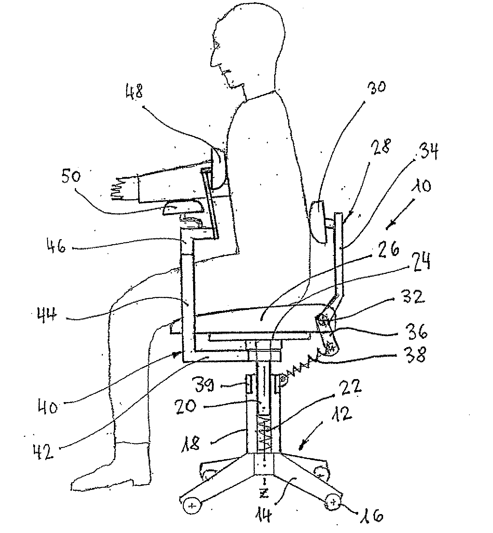
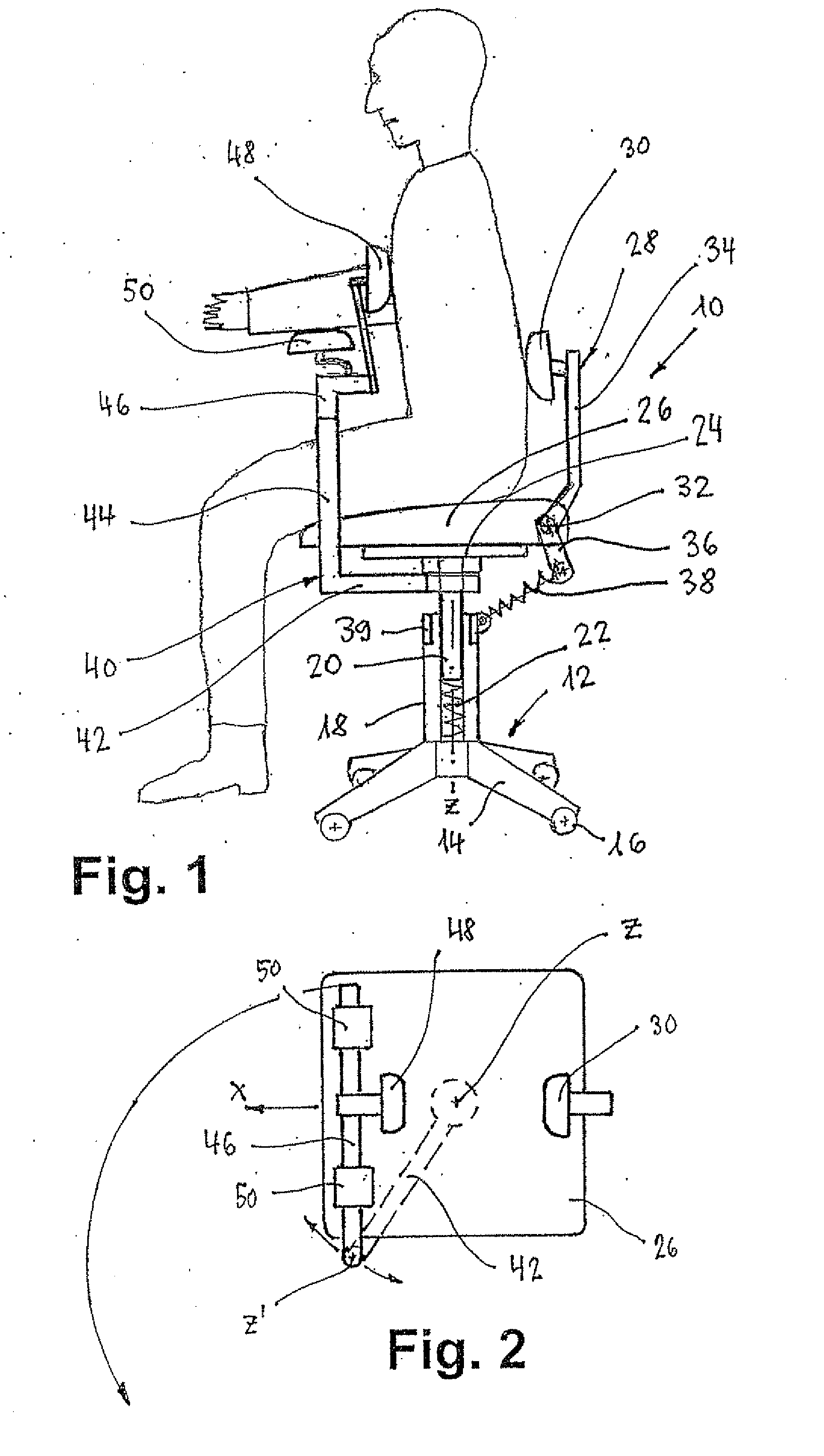
[0011]FIG. 1 the side view of a work chair in usage setting, having a lever mechanism for setting the angular position of the lumbar rest;

[0012]FIG. 2 the top view of the work chair of FIG. 1;

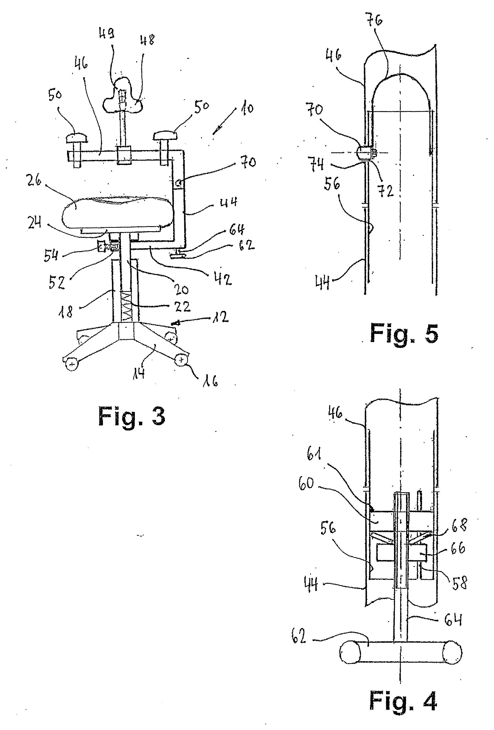
[0013]FIG. 3 the front view of the work chair of FIG. 1 without lumbar rest;

[0014]FIG. 4 a longitudinal section through a first detail of FIG. 3,

[0015]FIG. 5 a longitudinal section through a second detail of FIG. 3,

[0016]FIG. 6 an oblique view of a third detail of FIG. 3;

second embodiment

[0017]FIG. 7 the side view of a work chair without chest rest, having a lever mechanism for setting the angular position of the lumbar rest;

[0018]FIG. 8 the side view of a work chair without chest rest, having a lever mechanism in accordance with FIG. 7 with an additional adjustment facility for the angular position of the lumbar rest;

third embodiment

[0019]FIG. 9 the side view of a work chair without chest rest, having a lever mechanism for setting the angular position of the lumbar rest;

[0020]FIG. 10 the side view of a work chair without chest rest, having a third embodiment of a lever mechanism for setting the angular position of the lumbar rest;

[0021]FIG. 11 the front view of a variant of the work chair without chest rest, having an additional lumbar rest;

[0022]FIG. 12 the partially sectioned side view of a detail for adjusting the height and angular position of the chest rest.


PUM


Abstract

An ergonomic work chair for activities requiring a bent-forward posture has the following features: a supporting cylinder which protrudes from a star base, a supporting column, which is mounted in the supporting cylinder such that it can be displaced in a vertical cylinder axis, for a base plate with a seat which is fixed on the base plate, a base arm which is fitted to the supporting column or to the base plate, and a pivoting arm, which is mounted on the base arm such that it can be rotated out of the seat region about a vertical axis, having a chest rest and side arm rests, and a support which has a star rest and is hinge-connected to the base plate via a lever mechanism which has fulcrums such that pressing down on the seat causes the star rest to move in the direction of the chest rest.

Description

TECHNICAL FIELD OF THE INVENTION[0001]The present invention relates to an ergonomic work chair for the performance of activities in bent-forward posture.PRIOR ART[0002]In manual activities which are practiced in seated position with slightly bent-forward posture, such as, for example, in dentistry, the musculature in the small of the back—the sacro spinalis—is permanently tensed in order to keep the spinal column straight and absorb the torque upon the backbone. This leads to an increasing fatigue of the musculature, resulting in painful muscular strains (for example lumbago). Furthermore, declining muscle strength of the sacro spinalis can no longer hold the spinal column upright, with the result that this deviates rearward and passes into the so-called lordosis posture. This produces a permanent overstraining of the lower vertebrae and causes the chronic lower back pains which are widespread in our civilization.[0003]In a chair disclosed in EP-B-0 672 370, the lumbar rest is conne...

Claims


Application Information

Patent Timeline
Patent Type & Authority Applications(United States)
IPC IPC(8): A47C7/00
CPCA47C7/443A47C7/54A61B19/28A47C9/002A47C9/02A47C7/543A61B90/60A47C1/0308
Inventor ULRICH, HANS JURGEN
Owner ULRICH HANS JURGEN
Why Eureka
Try Eureka