Head moving mechanism and image forming apparatus

a head moving mechanism and image forming technology, applied in the direction of printing, inking apparatus, etc., can solve the problems of low speed of retracting movement using a cam mechanism, deterioration of movement accuracy, and problematically increasing so as to reduce the movement accuracy and the movement speed of the printhead, the effect of reducing the size of the head moving mechanism

Inactive Publication Date: 2009-12-03
SONY CORP
View PDF3 Cites 6 Cited by
  • Summary
  • Abstract
  • Description
  • Claims
  • Application Information

AI Technical Summary

Benefits of technology

[0014]In such a configuration, the space occupied by the foregoing mechanisms are minimized, and the printhead can be moved by using an appropriate one of the mechanisms. Consequently, the size of the head moving mechanism can be reduced without reducing the movement accuracy and the movement speed of the printhead.

Problems solved by technology

Therefore, if a head moving mechanism only employs cam mechanisms, the size of the head moving mechanism will problematically increase with a space accommodating such a large cam and a driving mechanism capable of rotating the large cam.
In addition, the speed of retracting movement using a cam mechanism is low.
In contrast, if a head moving mechanism is constituted by crank mechanisms and the like, instead of cam mechanisms, the movement accuracy will be deteriorated.
This may cause another problem in moving the thermal head up and down.

Method used


Image

  • Head moving mechanism and image forming apparatus
  • Head moving mechanism and image forming apparatus
  • Head moving mechanism and image forming apparatus

Examples


Embodiment Construction

[0020]An embodiment of the present invention will now be described with reference to the accompanying drawings.

[0021]The embodiment given below will be described taking a dye-sublimation thermal printer 1 as an example of the image forming apparatus according to the present invention, in which a mechanism corresponding to the head moving mechanism according to the present invention is included.

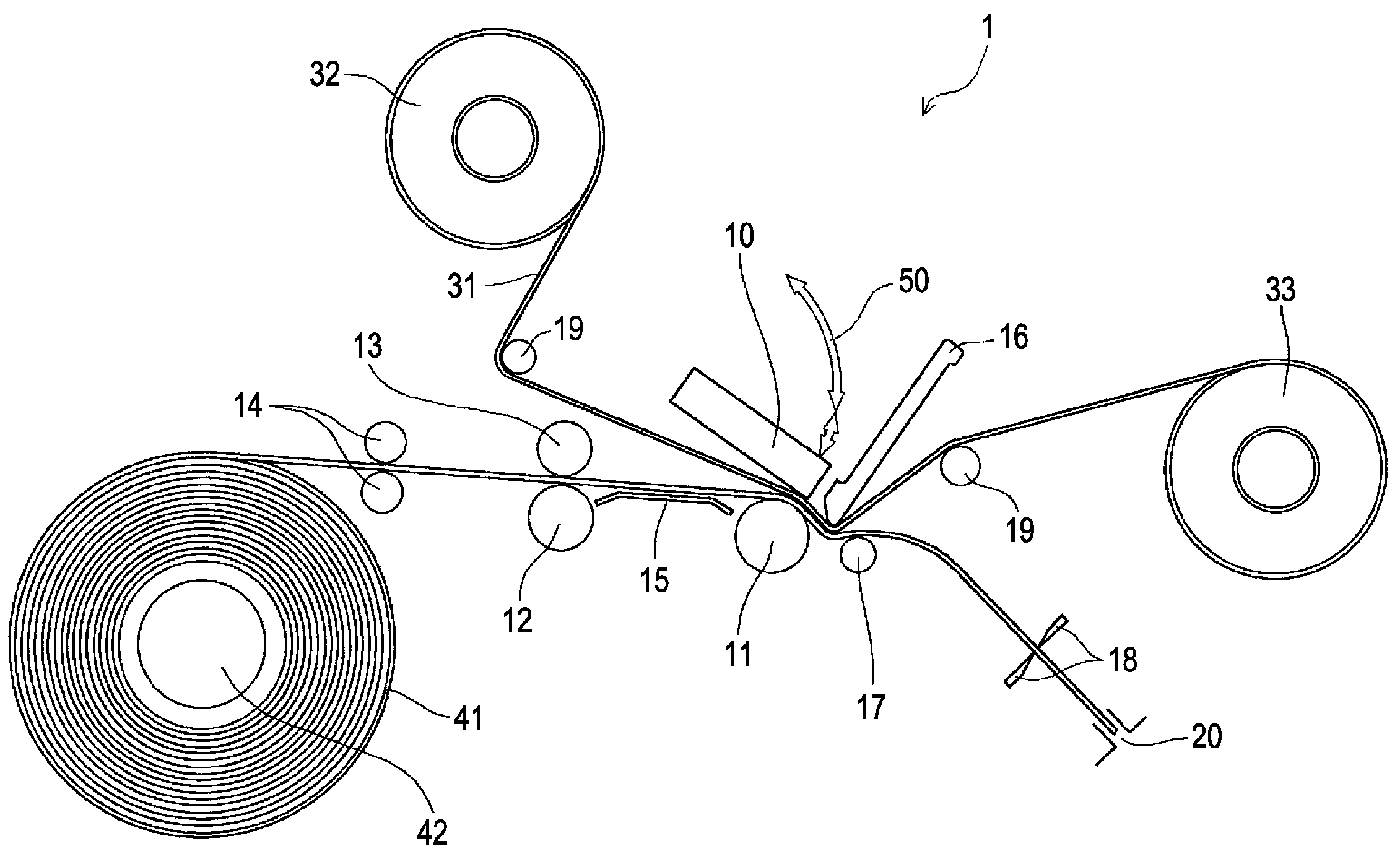
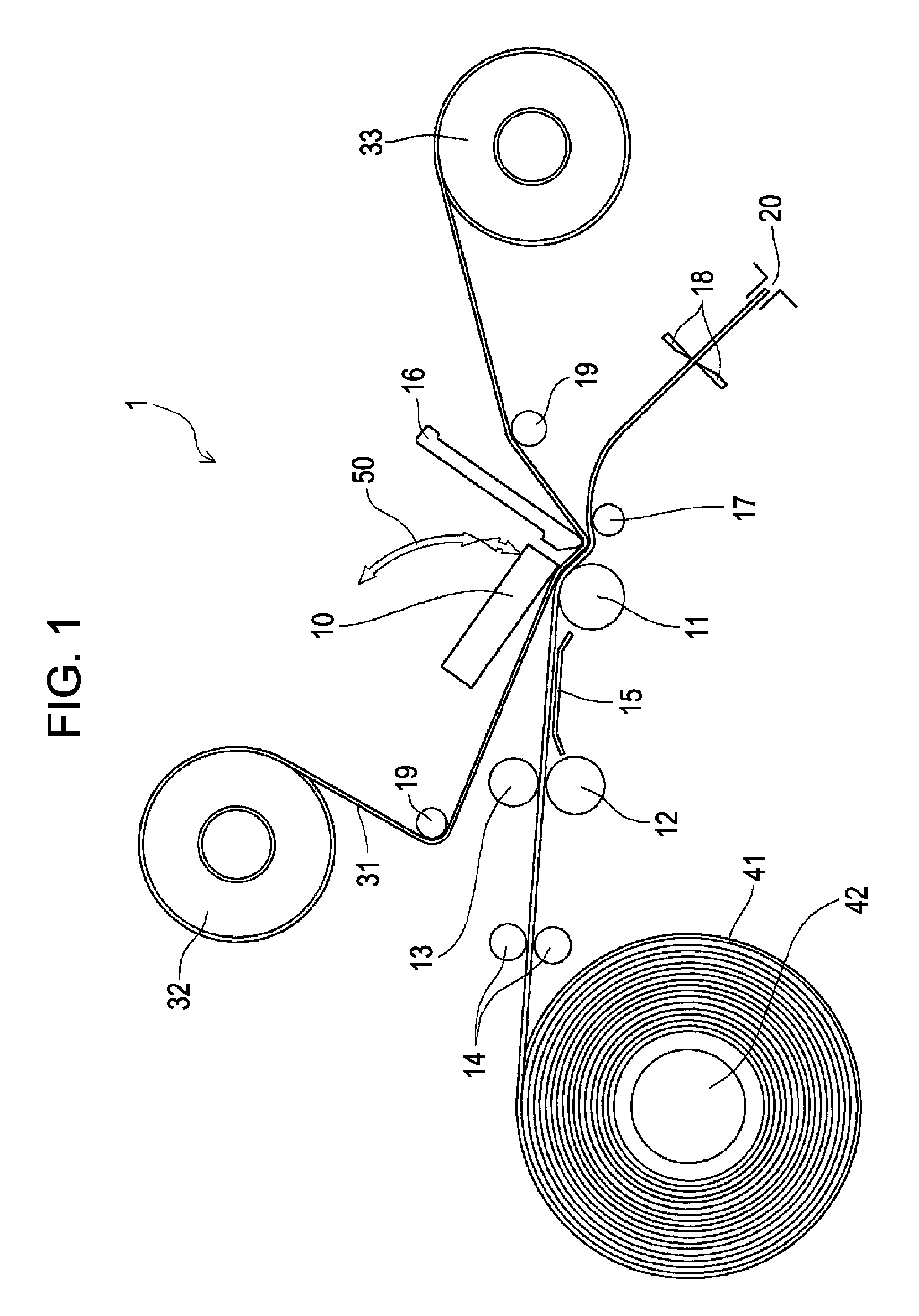
[0022]FIG. 1 is a side view showing the basic configuration of the thermal printer 1 according to the embodiment.

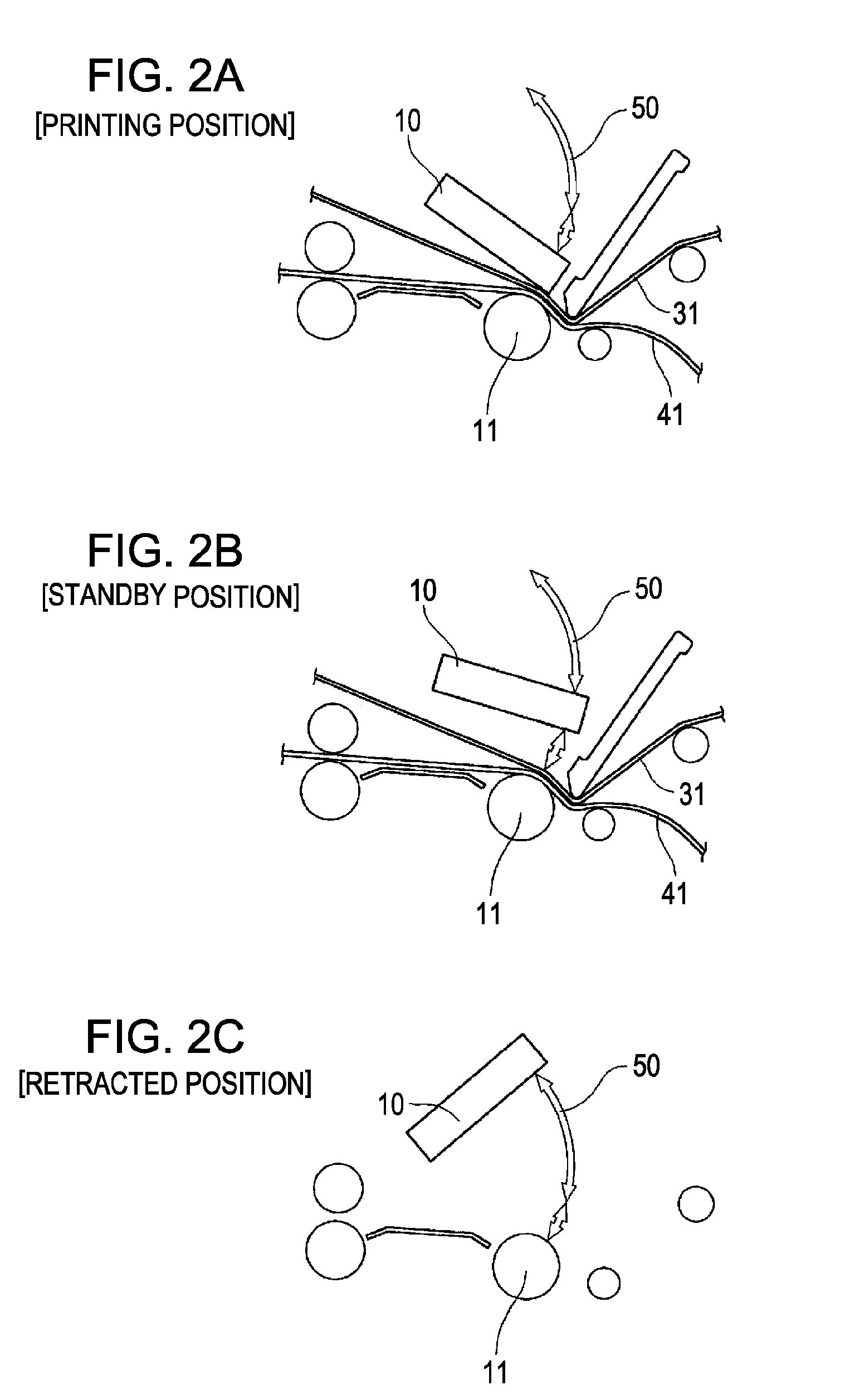
[0023]FIGS. 2A to 2C are side views of a thermal head 10 (corresponding to the print head according to the present invention) shown in FIG. 1, at a printing position, a standby position, and a retracted position, respectively.

[0024]Referring to FIGS. 1 to 2C, the thermal printer 1 according to the embodiment includes the thermal head 10, on which a plurality of heating elements (heating resistors, for example) are arranged in a line. With thermal energy generated when the heating el...


PUM


Abstract

A head moving mechanism includes a printhead configured to form an image and movable between a printing position where an image is formed, a standby position away from the printing position, and a retracted position across from the printing position relative to the standby position; a cam mechanism configured to move the printhead between the printing position and the standby position; and a rack-and-pinion mechanism configured to move the printhead between the standby position and the retracted position.

Description

BACKGROUND OF THE INVENTION[0001]1. Field of the Invention[0002]The present invention relates to head moving mechanisms each capable of moving a printhead between a printing position where an image is formed, a standby position where, for example, preparation for image formation is performed, and a retracted position where image formation is not performed, and also relates to image forming apparatuses. More specifically, the present invention relates to a technique in which the size of a head moving mechanism can be reduced without reducing the movement accuracy and the movement speed of a printhead.[0003]2. Description of the Related Art[0004]Common image forming apparatuses provided with printheads configured to form images include a printer, a copier, a facsimile, and the like. One of typical examples is a line thermal printer. The line thermal printer includes a thermal head, serving as a printhead, on which a plurality of heating elements, such as heating resistors, are arrange...

Claims


Application Information

Patent Timeline
Patent Type & Authority Applications(United States)
IPC IPC(8): B41J23/00
CPCB41J2202/31B41J2/325
Inventor KAMITANI, NOBUYUKI
Owner SONY CORP
Why Eureka
Try Eureka