Swirl Inducer

a technology of inducing structure and swirl, which is applied in the field of swirl inducing structure, can solve the problems of reducing the overall efficiency of fluid flow through requiring additional force, and stagnant fluid contained by the tube or du

Inactive Publication Date: 2009-12-17
PAX STREAMLINE +1
View PDF101 Cites 17 Cited by
  • Summary
  • Abstract
  • Description
  • Claims
  • Application Information

AI Technical Summary

Problems solved by technology

Introducing a swirl inducing device into a flow path, however, reduces the overall efficiency of the fluid flow through the tube or duct.
Unsatisfactory degrees of drag and friction are generated thereby requiring additional force to maintain requisite fluid flow.
Areas of backpressure may also result thereby resulting in stagnant zones of fluid contained by a tube or duct.
Such prior art arrangements also create blockages within the tube or duct through the buildup of scale or similar deposits on the surfaces of the swirl inducers and / or in the tube or duct.
These buildups and deposits lend to the inevitable need for repairs and cleanouts, which result in certain fluid pathways being taken entirely out of operation.
The efficiency of prior art swirl inducing structures in effectuating heat transfer is limited, however, as prior art swirl inducing structures require considerable surface area.
These large structures are not particularly efficient due to the restrictions that they present to the flow of the fluid past the swirl inducing structure not to mention the requisite size of a corresponding duct or tube.

Method used


Image

  • Swirl Inducer
  • Swirl Inducer
  • Swirl Inducer

Examples


Embodiment Construction

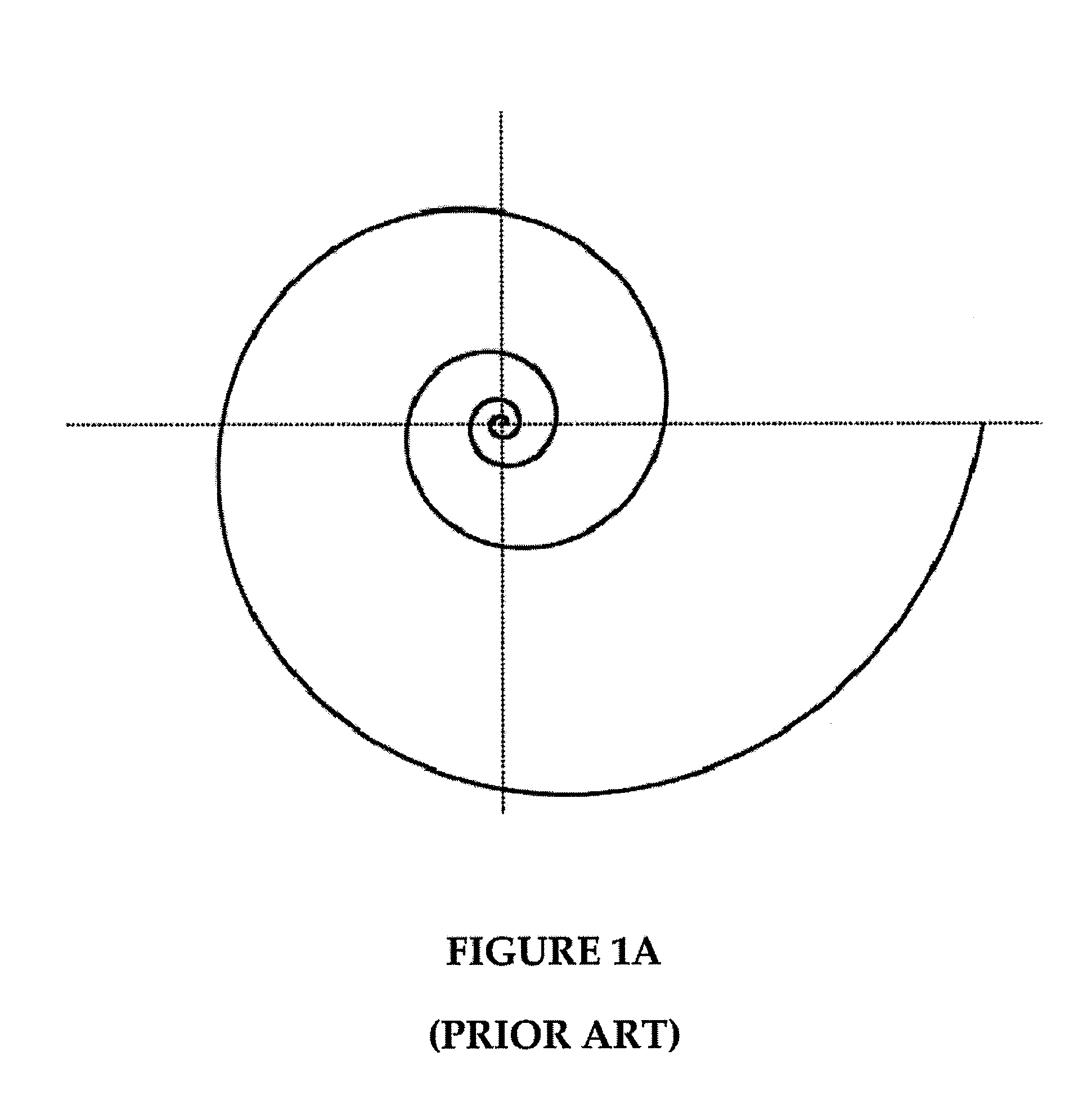
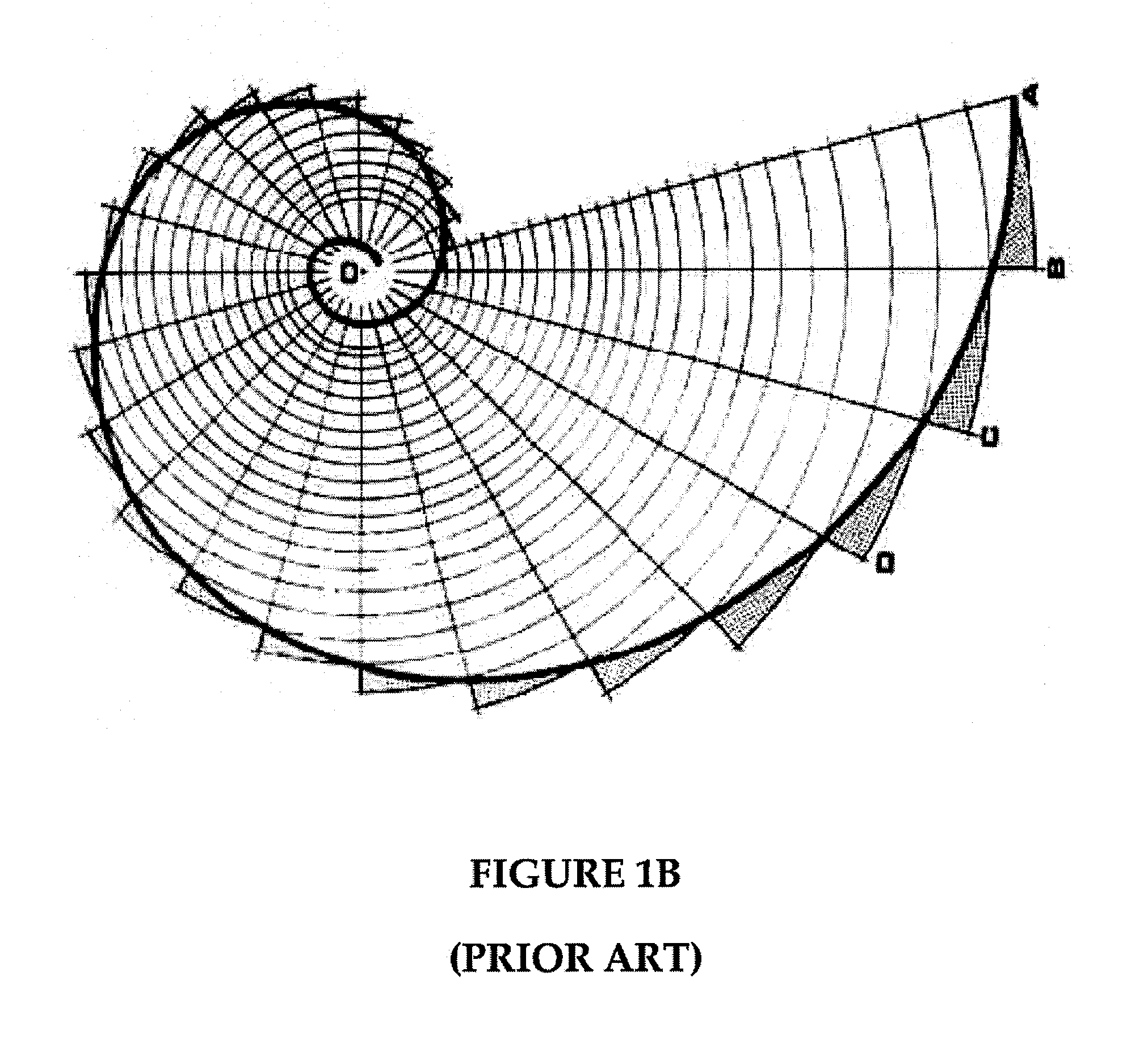
[0025]FIG. 1A illustrates a logarithmic spiral, as known in the prior art. FIG. 1B, however, illustrates a particular type of logarithmic spiral, also known in the art, wherein the radius of the logarithmic spiral measured at equiangular radii unfolds at a constant order of growth. A logarithmic spiral (sometimes referred to as an equiangular spiral or growth spiral) like that of FIG. 1A is a special kind of spiral curve that often appears in nature. A Golden Spiral—a spiral in accord with the Golden Section or Golden Ratio—like that depicted in FIG. 1B is a type of logarithmic spiral where two quantities are in golden ratio. Two quantities are in golden ratio or embody the Golden Ratio if the ratio of the sum of the quantities to the larger one equals the ratio of the larger one to the smaller. The golden ratio is an irrational mathematical constant, which approximates 1.6180339887 and is often denoted by the Greek letter phi (φ).

[0026]This constant, when expressed algebraically re...


PUM


Abstract

A swirl inducer or mixer for location within a tube or duct. The swirl inducer may extend within the tube or duct and has an active surface over which a fluid flows to induce a swirling vortical flow within the fluid. The swirl inducer induces vortical flow in the tube or duct, which conforms with the path of least resistance and minimizes the amount of energy that is applied to the fluid to cause it to flow through the tube or duct and that causes the greatest, most rapid mixing of fluids passing through the tube or duct.

Description

CROSS-REFERENCE TO RELATED APPLICATIONS[0001]The present application claims the priority benefit of U.S. provisional patent application No. 61 / 061,630 filed Jun. 15, 2008 and entitled “Swirl Inducer.” The disclosure of the aforementioned application is incorporated herein by reference.BACKGROUND OF THE INVENTION[0002]1. Field of the Invention[0003]The present invention generally relates to fluid mechanics. More specifically, the present invention relates to a swirl inducing structure, which may be located in a tube or duct.[0004]2. Description of the Related Art[0005]Fluid flow within a tube or duct is generally most efficient when in a state of laminar flow. In certain situations, however, it is necessary for the fluid to be in a state of non-laminar flow. Such a situation includes a tube or duct involved in the exchange of heat between the tube or duct walls and a fluid whereby inducing a certain degree of turbulence in the flow may lend to an increase in the mixing of fluids ther...

Claims


Application Information

Patent Timeline
Patent Type & Authority Applications(United States)
IPC IPC(8): F15C1/16
CPCB01F2005/0633B01F5/0615Y10T137/2087B01F25/431951B01F25/43141
Inventor HARMAN, JAYDEN DAVID
Owner PAX STREAMLINE
Why Eureka
Try Eureka