Clamping device for workpieces with different sizes

a technology of workpieces and clamping devices, which is applied in the direction of manufacturing tools, drawing boards, printing, etc., can solve the problems of reducing the efficiency of machining flat panels and increasing costs

Inactive Publication Date: 2009-12-17
HON HAI PRECISION IND CO LTD
View PDF4 Cites 22 Cited by
  • Summary
  • Abstract
  • Description
  • Claims
  • Application Information

AI Technical Summary

Problems solved by technology

This may increase costs and reduce the

Method used


Image

  • Clamping device for workpieces with different sizes
  • Clamping device for workpieces with different sizes
  • Clamping device for workpieces with different sizes

Examples


Embodiment Construction

[0013]Reference will now be made to the drawings to describe various embodiments of the present clamping device.

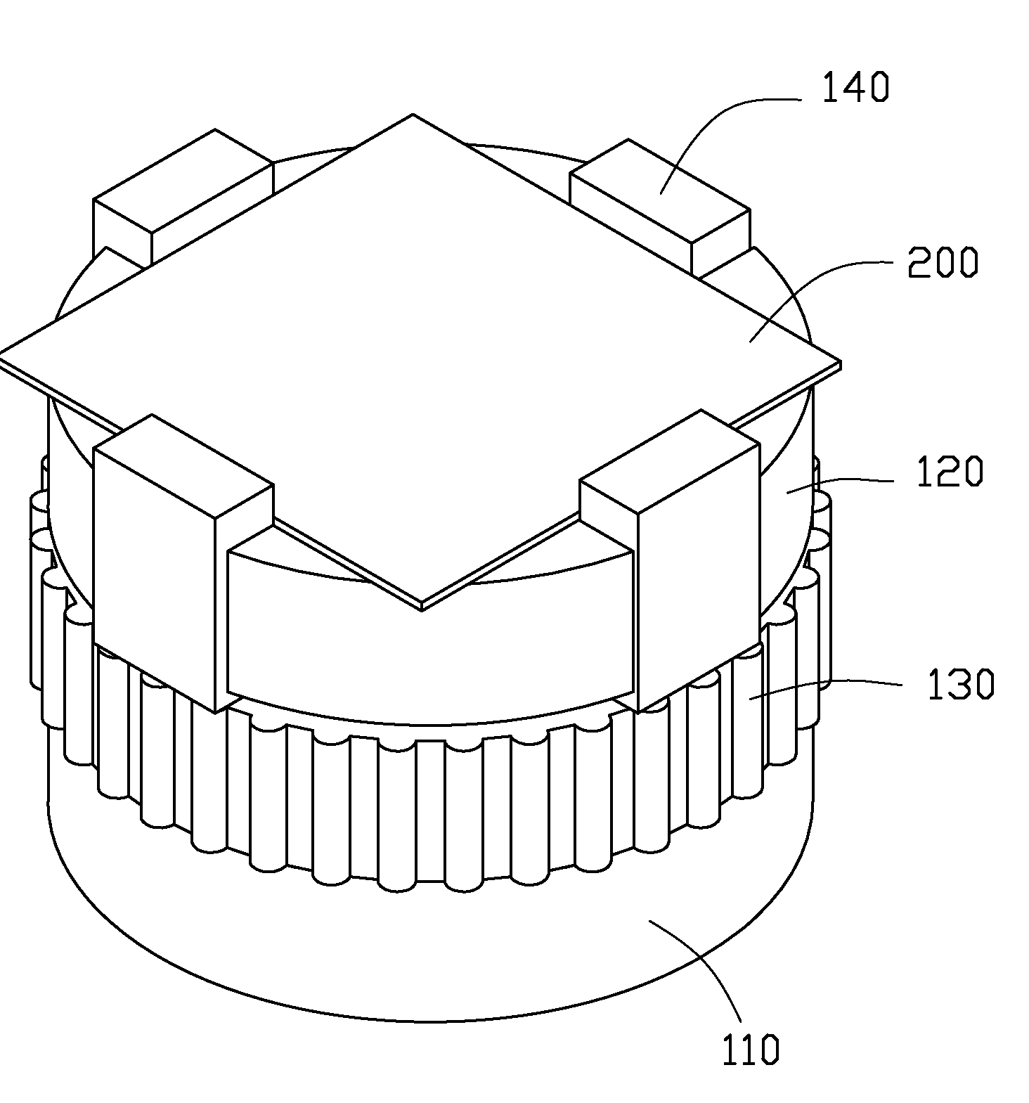
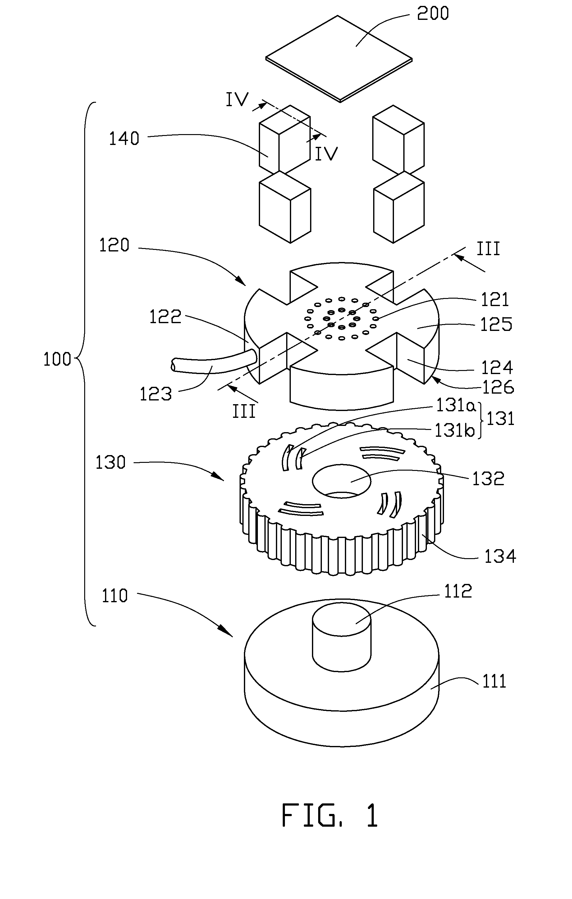
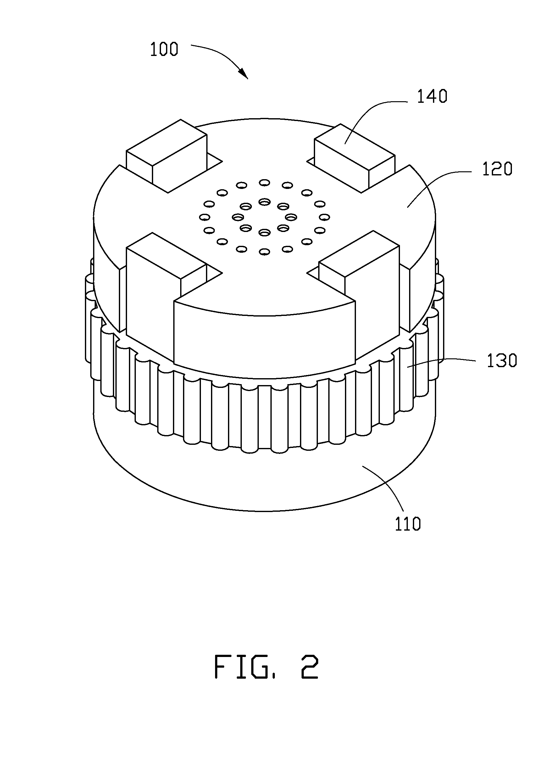
[0014]Referring to FIGS. 1 and 2, a clamping device 100 in accordance with an exemplary embodiment is shown. The clamping device 100 is for clamping a workpiece 200. The clamping device 100 includes a base 110, a support member 120, a rotating member 130, and four sliding members 140.

[0015]The base 110 includes a main body 111, and a pivot 112 integrally formed on top of the main body 111. In this embodiment, the main body 111 and the pivot 112 are coaxial with each other. A radius of the main body 111 is greater than a radius of the pivot 112. In the illustrated embodiment, each of the main body 111 and the pivot 112 is in the form of a short cylinder.

[0016]The rotating member 130 has a generally cylindrical shape, and defines a through hole 132 in the center thereof. In this embodiment, the through hole 132 has a cylindrical shape and is coaxial with a central axis of th...


PUM


Abstract

A clamping device for clamping a workpiece includes a support member, sliding members and a rotating member. The support member is configured for supporting the workpiece. The support member defines cutouts in a periphery thereof. The sliding members each is positioned in one of the cutouts. Each of the sliding members has a cam pin. The rotating member is rotatable relative to the support member. The rotating member defines cam slots on top thereof. The cam pins are received in the cam slots and slidable in the cam slots. Positions of the sliding members are changeable along radial directions of the support member when the rotating member is rotated.

Description

BACKGROUND[0001]1. Technical Field[0002]The present invention relates to clamping devices, and particularly to a clamping device for clamping workpieces such as flat panels.[0003]2. Description of Related Art[0004]When machining a workpiece, such as a flat panel, the flat panel should be fastened on a support member of a clamping device. Flat panels with different sizes typically require different support members. This may increase costs and reduce the efficiency of machining the flat panels.[0005]What is needed, therefore, is a clamping device that can overcome the above shortcomings.BRIEF DESCRIPTION OF THE DRAWINGS[0006]Many aspects of the present clamping device can be better understood with reference to the following drawings. The components in the drawings are not necessarily drawn to scale, the emphasis instead being placed upon clearly illustrating the principles of the present clamping device. Moreover, in the drawings, like reference numerals designate corresponding parts ...

Claims


Application Information

Patent Timeline
IPC IPC(8): B25B1/02B25B1/08B25B1/20B23Q3/06
CPCB23Q2240/002B23Q3/062
Inventor WANG, CHUN-KAI
Owner HON HAI PRECISION IND CO LTD
Why Eureka
Try Eureka