Bone plate with complex, adjacent holes joined by a bend relief zone

a bone plate and complex technology, applied in the field of bone plates, can solve the problems of reducing surgical flexibility, increasing complexity of procedures, and requiring more operating room time, and achieve the effect of greater flexibility of choi

Inactive Publication Date: 2009-12-24
SWISS PRO ORTHOPEDIC
View PDF14 Cites 165 Cited by
  • Summary
  • Abstract
  • Description
  • Claims
  • Application Information

AI Technical Summary

Benefits of technology

[0018]An object of the invention is to provide a surgeon with the option of placing two bone screws in abutting adjacent positions. Another object of the invention is to provide an orthopaedic surgeon greater flexibility of choice in

Problems solved by technology

Although an improvement over the inserts noted above, the locking positions are pre-defined and only available in limited locations, which also reduce surgical flexibility.
This is not desirable because this requires more operating room time and adds complexity to the procedure.
Further, the inserts must be added in the specific location before the plate is fixed to the bone and cannot be subsequently inserted.
This limits the choice of placement during surgery if the need arises.
Simple surface friction locks are not reliable and come loose more easily than threaded locked holes.
The result of such a design is inferior to that of the threaded plate and sc

Method used


Image

  • Bone plate with complex, adjacent holes joined by a bend relief zone
  • Bone plate with complex, adjacent holes joined by a bend relief zone
  • Bone plate with complex, adjacent holes joined by a bend relief zone

Examples


Embodiment Construction

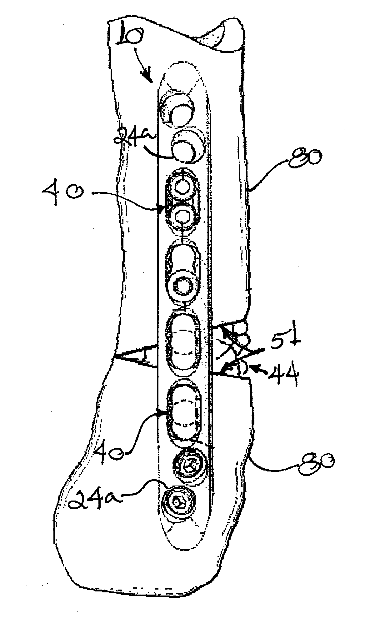
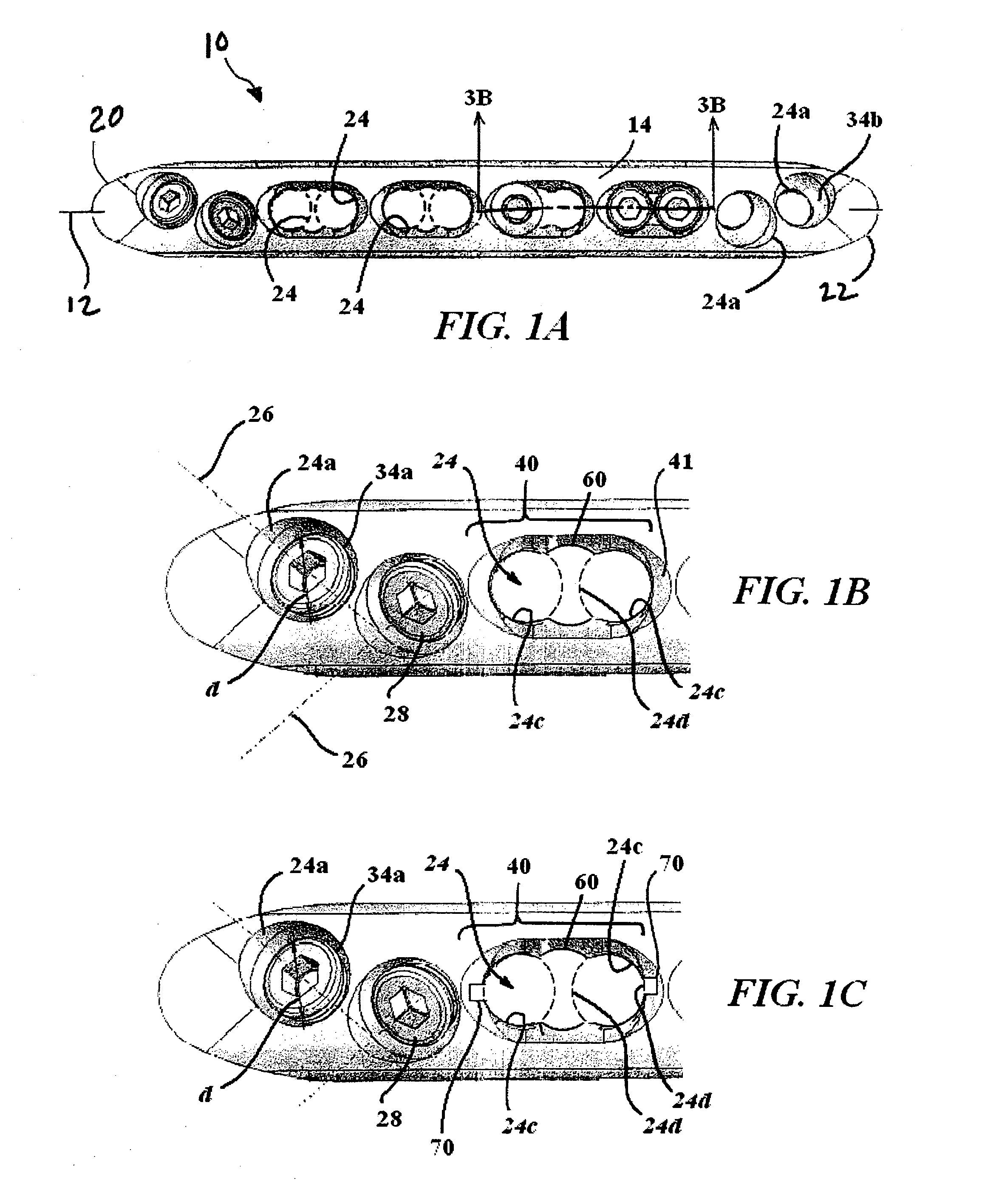
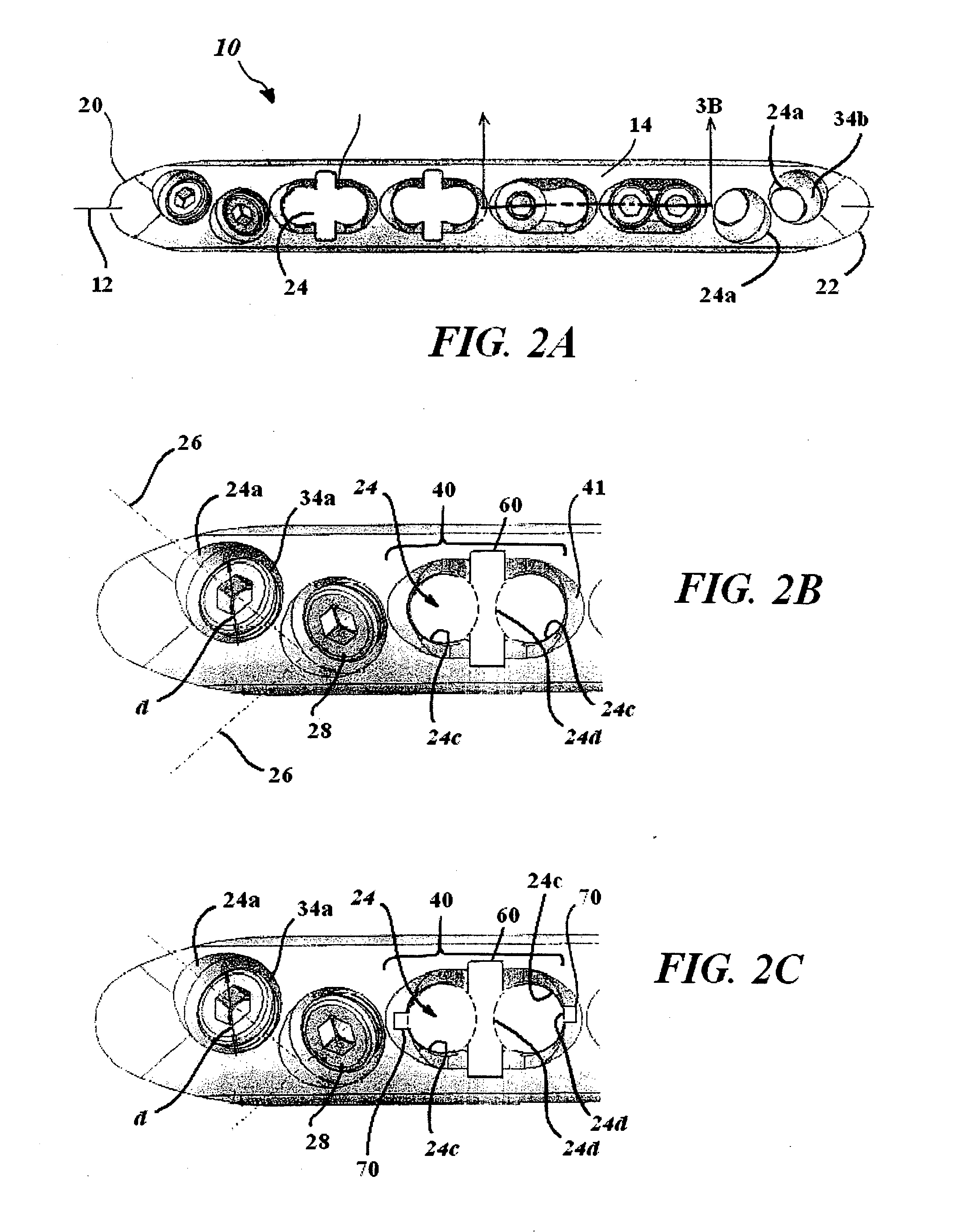
[0030]Referring now to the drawings, the details of preferred embodiments of the present invention are graphically and schematically illustrated. Like elements in the drawings are represented by like numbers, and any similar elements are represented by like numbers with a different lower case letter suffix.

[0031]As exemplified in FIGS. 1A and 2A, the present bone plate 10 has a main longitudinal axis 12, a bone-contacting bottom side 16 (see FIG. 4), a top side 14 and opposite first 20 and second 22 plate ends. A series of screw apertures 24 extending from the top side 14 of the plate 10 through to its bottom side 16 are formed along the plate axis 12. The screw apertures 24 serve as bone screw guides through which points bone screws 28 are inserted into underlying bone to anchor the bone plate 10 to different parts or fragments of a bone 80 to be reinforced by the bone plate 10 (see FIG. 5). The screw apertures 24 have a screw axis 26 (the general path that a screw takes when inser...


PUM


Abstract

A bendable bone plate (10) is disclosed which is adapted for use in situ as a conformable bone splint to fix the spatial relationship of at least two bone parts (80). The bone plate (10) has an elongated plate (11) made of a bendable material. A plurality of screw apertures (24) extending through the top (14) and bottom (16) surfaces are disposed along the length (L) of the plate. Bone screws (28) are inserted through the apertures into the underlying bone parts (80) to anchor the elongated plate (11) to the bone parts (80). At least two of the screw apertures (24) are disposed as a closely spaced pair (40) of screw apertures (24) with a “bend relief zone” (60) disposed between the closely spaced apart screw apertures (24). The bend relief zone (60) is disposed to allow the elongated plate (11) to be bent across the bend relief zone (60) up to a certain angle (A) without deforming the screw apertures (24) adjacent the bend relief zone (60)

Description

CROSS-REFERENCE TO RELATED APPLICATIONS[0001]The present application claims the benefit of prior filed U.S. Provisional Patent Application, Ser. Nos. 60 / 806,731 filed 7 Jul. 2006, and 60 / 806,733 also filed 7 Jul. 2006, which applications are incorporated herein by reference.FIELD OF THE INVENTION[0002]The present invention is in the field of surgically implanted orthopedic devices, implants and prostheses used in orthopedic surgery. More specifically, the present invention relates to bone plates used to reinforce fractured bones and thus to promote healing.BACKGROUND OF THE INVENTION[0003]A compressive screw system, also known as the DCS system, is a bone plate system that has been used in trauma surgery for many years. The procedures for use of this system are well documented by the AO Institute (Davos, Switzerland), an institute having as one of its goals, the promotion of new orthopedic surgical procedures. This system included a bone plate having slots communicating therethrough...

Claims


Application Information

Patent Timeline
IPC IPC(8): A61B17/80
CPCA61B17/1728A61B17/8085A61B17/8057
Inventor WHITE, PATRICKBERDOZ, PATRICKFORBES, STEVE
Owner SWISS PRO ORTHOPEDIC
Why Eureka
Try Eureka