Metal composite for fuel cell and fuel cell bipolar plate using same, and fabrication method for same

a technology of bipolar plate and fuel cell, which is applied in the direction of cell components, sustainable manufacturing/processing, semiconductor/solid-state device details, etc., can solve the problems of increasing the number of components and manufacturing costs, dissolving (corrosion) of the core material, and inability to freely use the bipolar plate of consumer fuel cells. , to achieve the effect of greater flexibility of core material choi

Inactive Publication Date: 2011-01-18
HITACHI CABLE
View PDF6 Cites 5 Cited by
  • Summary
  • Abstract
  • Description
  • Claims
  • Application Information

AI Technical Summary

Benefits of technology

[0021]The metal composite according to the invention provides extended service lives of fuel cell components such as bipolar plates and greater flexibility of choice of the core material.

Problems solved by technology

However, corrosion resistant metals are very expensive and therefore cannot be used freely for bipolar plates of consumer fuel cells.
A problem with conventional metal composites for fuel cells is that the hole wall of the core layer region of the through-hole is exposed to the ambient environment, and therefore dissolution (corrosion) of the core material can occur due to dew condensation or a pH change caused by impurity ions contained in the oxidant gas.
Furthermore, when an Al (aluminum) is employed as the core metal in order to reduce the weight of a bipolar plate, more reliable anti-corrosion protection is needed because the Al is far less resistant to such core dissolution than a stainless steel.
However, the method according to the above JP-A-2005-158441 covers each through-hole individually, and therefore can cause an increase in the number of components and the manufacturing cost.
Further, in this method, the resin film can block the through-hole, or can thicken the portion of the bipolar plate surrounding each through-hole, thus possibly incurring assembly difficulty.

Method used


Image

  • Metal composite for fuel cell and fuel cell bipolar plate using same, and fabrication method for same
  • Metal composite for fuel cell and fuel cell bipolar plate using same, and fabrication method for same
  • Metal composite for fuel cell and fuel cell bipolar plate using same, and fabrication method for same

Examples


first embodiment

of the Invention

[0031](Structure of Metal Composite)

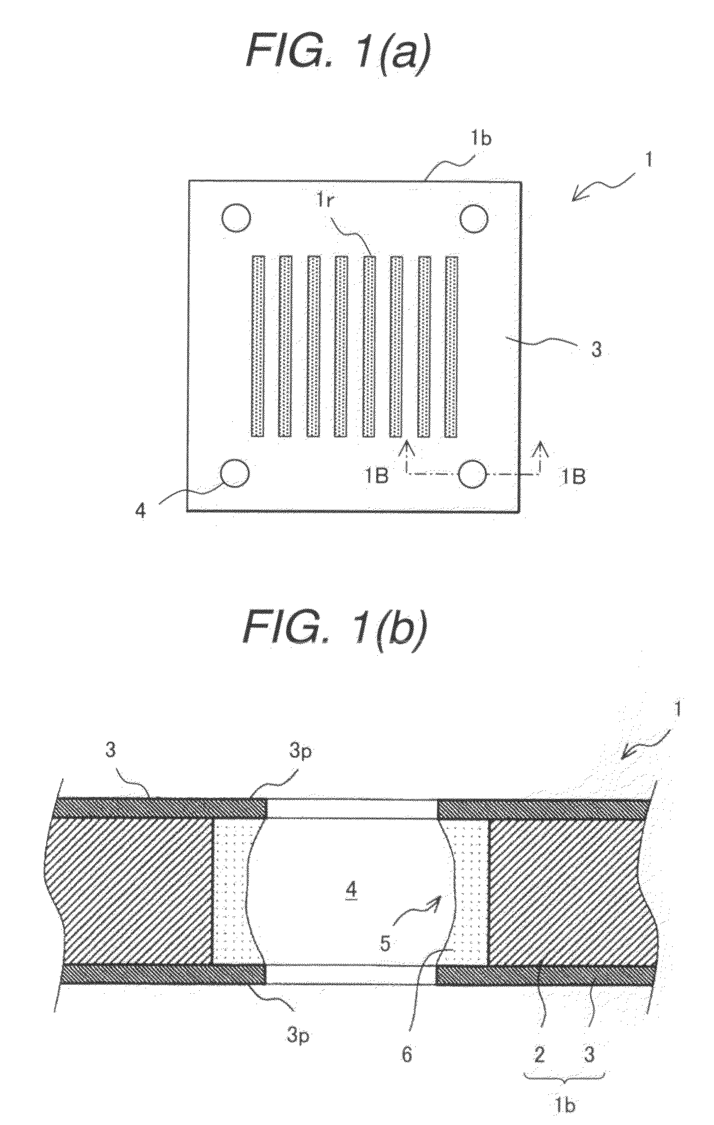
[0032]FIG. 1(a) is a schematic illustration showing a plan view of a metal composite for fuel cells according to a first preferred embodiment of the present invention; and FIG. 1(b) is a schematic illustration showing a cross-sectional view along 1B-1B line in FIG. 1(a).

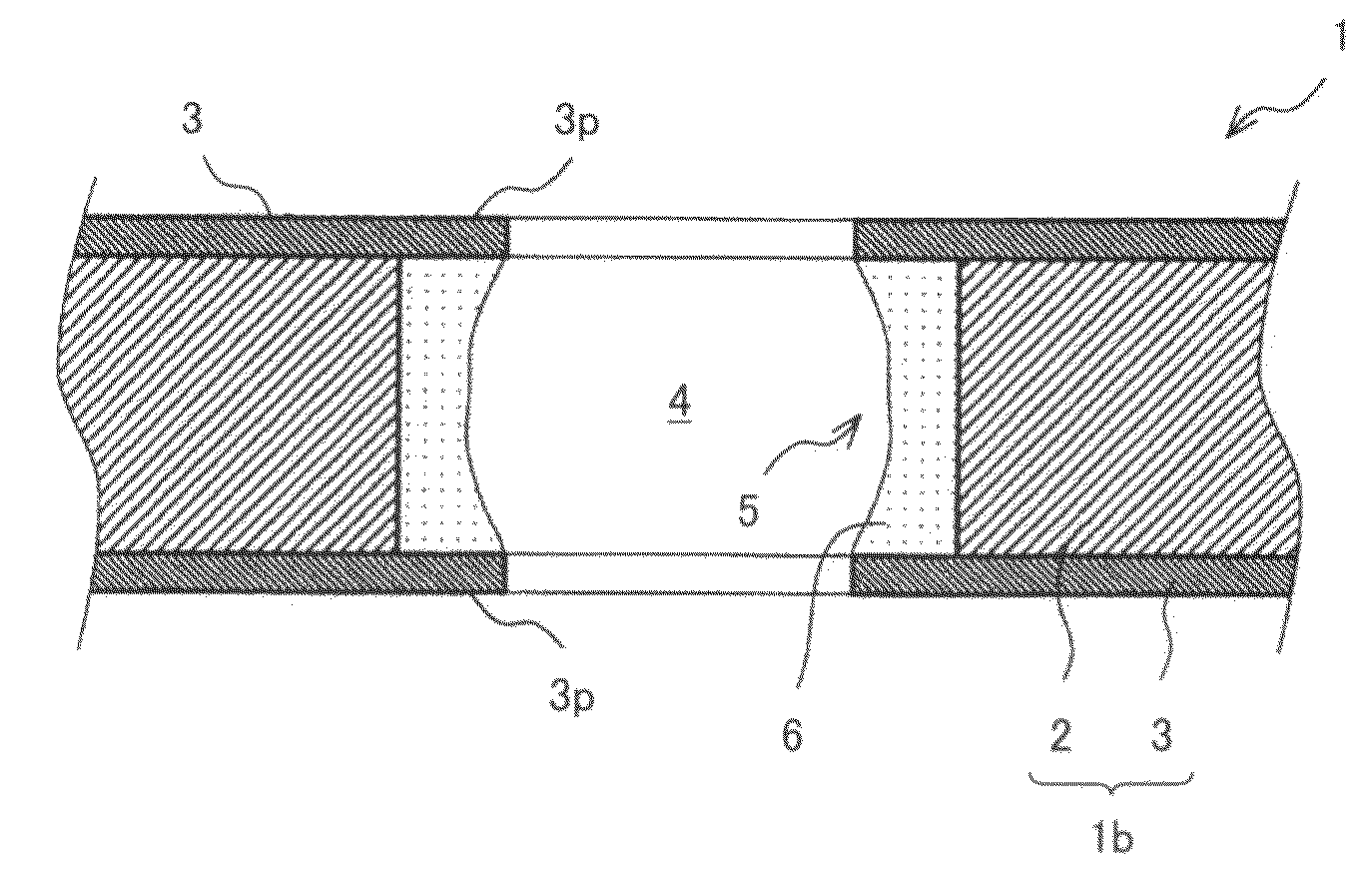
[0033]As shown in FIGS. 1(a) and 1(b), a metal composite 1 for fuel cells according to the first embodiment includes: a core 2 of a metal plate; cladded layers (corrosion resistant cladded layers) 3 covering both surfaces of the core 2; and through-holes 4 penetrating both the core 2 and cladded layers 3 in the thickness direction (perpendicular to the drawing plane of FIG. 1(a) and vertical direction as viewed in FIG. 1(b)). In addition, on a hole wall of the core 2 region of each through-hole 4 of the metal composite 1, there is formed a circumferentially-extending concave portion 5 that is recessed relative to a hole wall of the cladded layer 3 regions on both si...

second embodiment

of the Invention

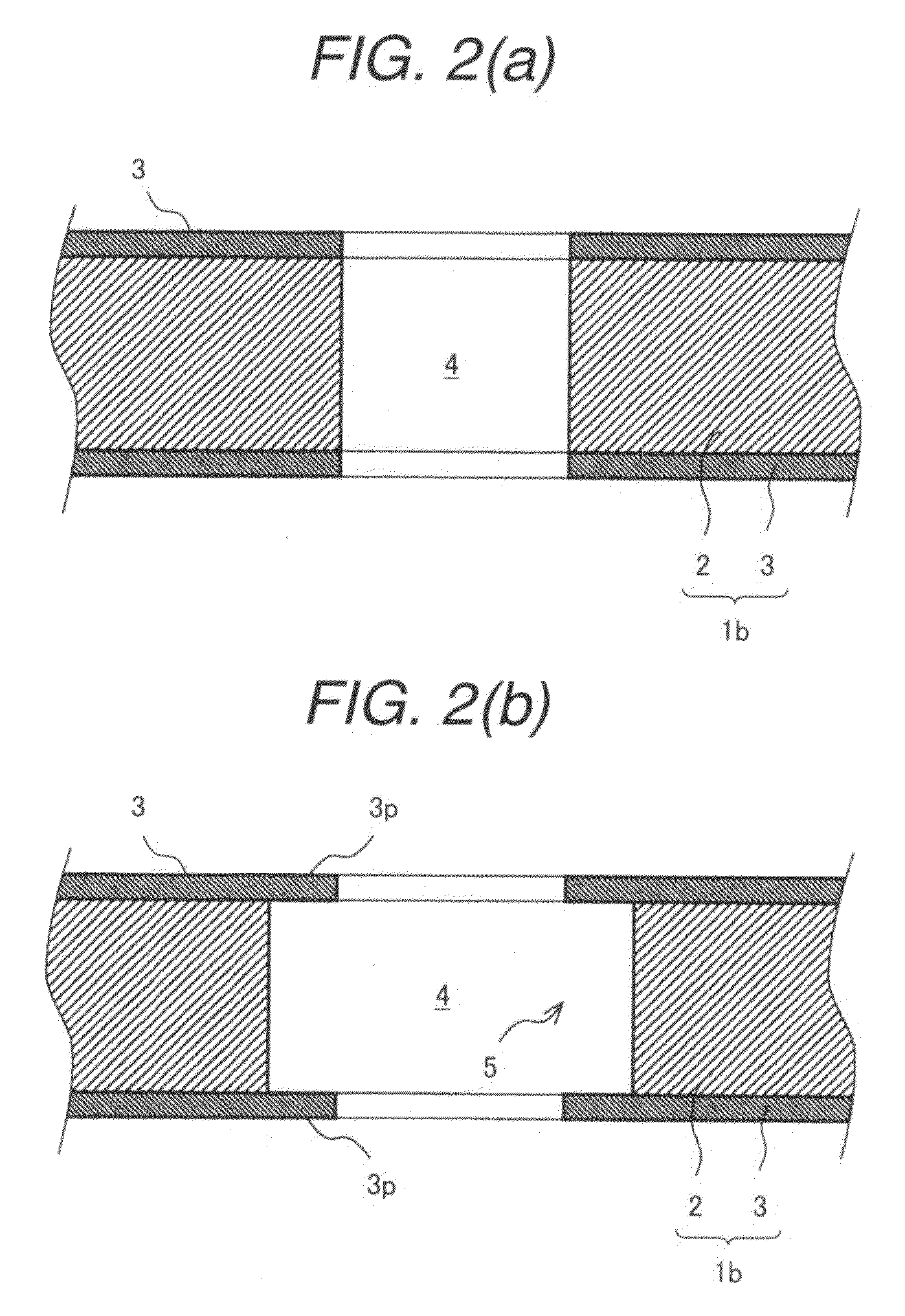
[0061]A second embodiment of the present invention will be described. FIG. 7(a) is a schematic illustration showing a cross-sectional view of an exemplary fabricating method of a metal composite for fuel cells according to a second embodiment of the present invention; and FIG. 7(b) is a schematic illustration showing a cross-sectional view of a principal portion of the metal composite according to the second embodiment.

[0062]As shown in FIG. 7(b), in a metal composite 51 for fuel cells according to the second embodiment, a concave portion 5 is formed in each through-hole 4 similarly to the first embodiment shown in FIG. 2(b). Unlike the first embodiment, the projected hole wall portion (corresponding to the projection portion 3p in FIG. 2(b)) of the cladded layer regions of each through-hole 4 is bent inwardly to form a bent projection 3f. And, a dissolution-inhibiting material 6 is filled into the space of the concave portion 5 sandwiched between both bent projectio...


PUM

PropertyMeasurementUnit
corrosion resistantaaaaaaaaaa
power generation characteristicsaaaaaaaaaa
pHaaaaaaaaaa

Abstract

A metal composite for fuel cells according to the present invention, which includes: a core of a metal; cladded layers of a corrosion resistant metal covering both surfaces of the core; and a through-hole formed through the core and cladded layers. The through-hole has, on a hole wall of the core region of the through-hole, a concave portion which is recessed relative to hole walls of the cladded layer regions of the through-hole.

Description

CLAIM OF PRIORITY[0001]The present application claims priority from Japanese patent application serial no. 2007-243963 filed on Sep. 20, 2007, the content of which is hereby incorporated by reference into this application.BACKGROUND OF THE INVENTION[0002]1. Field of the Invention[0003]The present invention relates to metal composites for fuel cells, which have a core cladded with a corrosion resistant metal and have through-holes formed therethrough, and fuel cell bipolar plates fabricated from such a metal composite. The present invention also relates to fabrication methods for the metal composites.[0004]2. Description of Related Art[0005]Conventionally, metal composites formed by laminating and bonding a plurality of metals are used in various fields. In particular, materials having a Ti (titanium) surface layer are being developed for use in fuel cell bipolar plates exposed to harsh corrosive environments. Examples of prior patent documents which disclose a fuel cell bipolar plat...

Claims


Application Information

Patent Timeline
Patent Type & Authority Patents(United States)
IPC IPC(8): H01M8/04H01M2/18B21C1/00C23F1/00B44C1/00C25D5/02
CPCH01M8/0206H01M8/0228H01M8/0258Y10T428/12229Y02E60/50Y02P70/50H01M8/2483
Inventor WASHIMA, MINEOSASAOKA, TAKAAKISEIDO, MASAHIRONAKAGAWA, KAZUHIKO
Owner HITACHI CABLE
Why Eureka
Try Eureka