Eureka AIR delivers breakthrough ideas for toughest innovation challenges, trusted by R&D personnel around the world.

Energy storing foot plate

a foot plate and energy storage technology, applied in the field of prosthetic devices, can solve the problems of storing less energy, releasing too late, and causing serious injury

Active Publication Date: 2009-12-24
MOTION CONTROL
View PDF16 Cites 17 Cited by
  • Summary
  • Abstract
  • Description
  • Claims
  • Application Information

AI Technical Summary

Benefits of technology

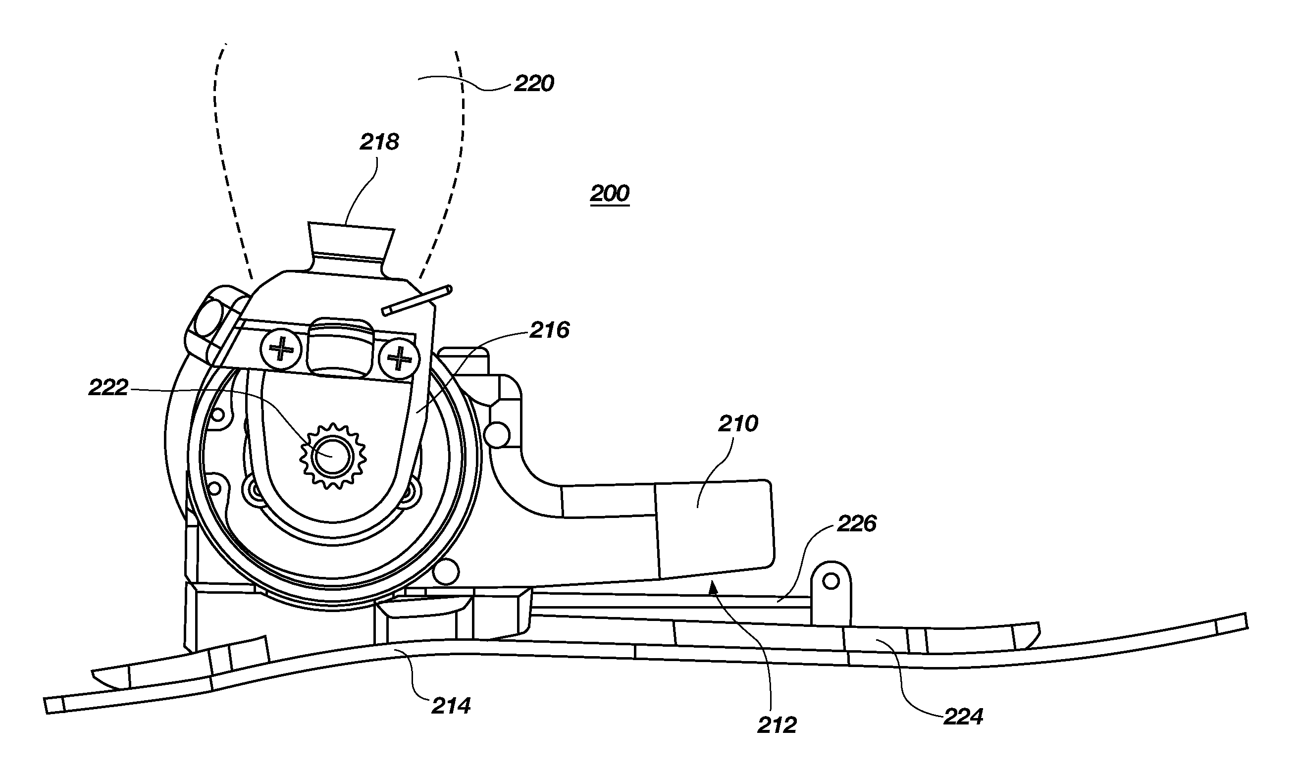
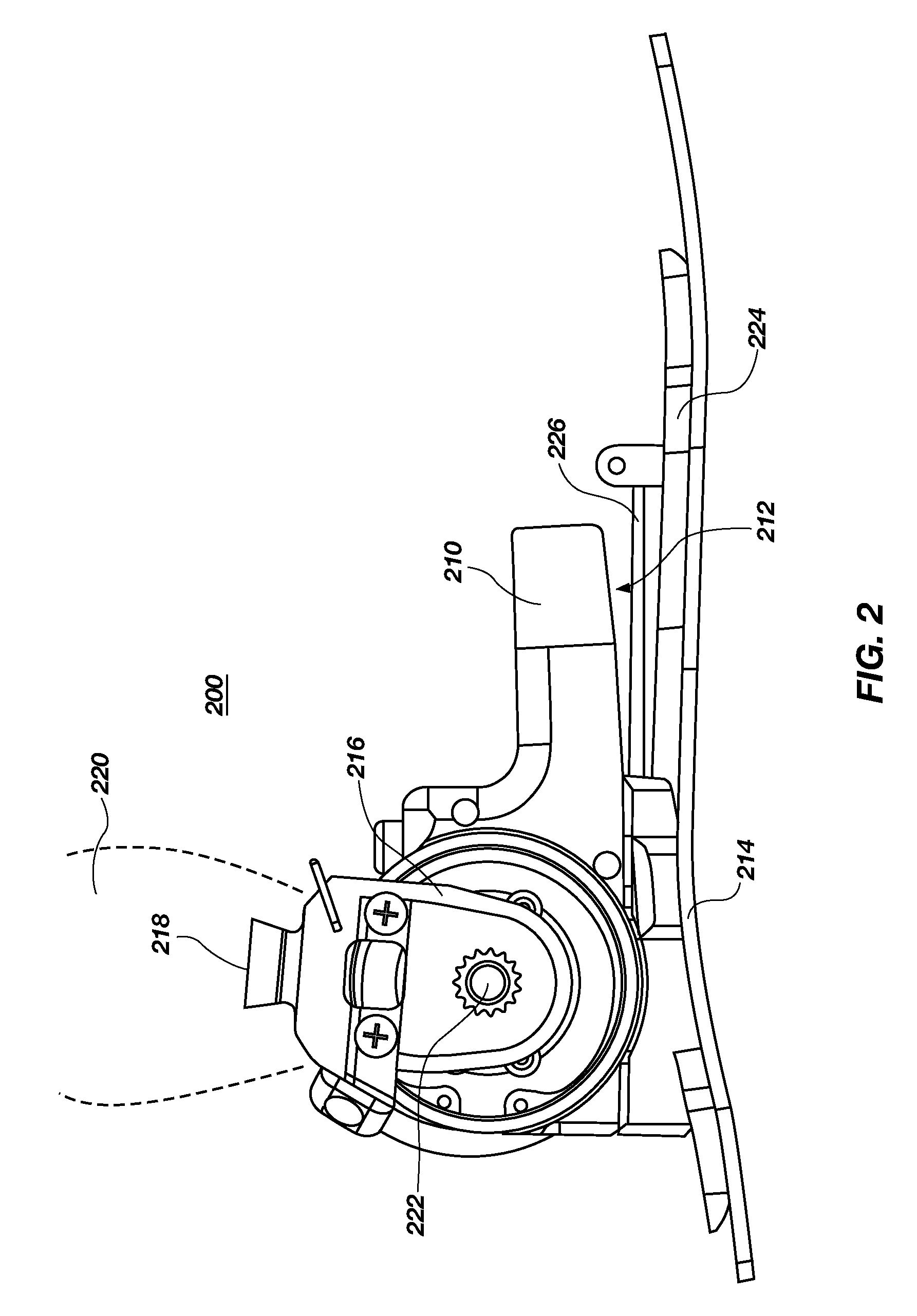
"The present invention relates to prosthetic ankle and foot devices. The invention includes a joint housing with a curved bottom surface that allows for flexion of a substrate when coupled to the joint housing. The invention also includes a clevis that can rotate about the joint housing and a prosthetic coupling structure that connects the clevis to an amputee. The invention further includes a toe-off spring, a toe-lift spring, and a rotary hub that acts as an articulating joint. The invention provides improved flexibility and comfort for amputees."

Problems solved by technology

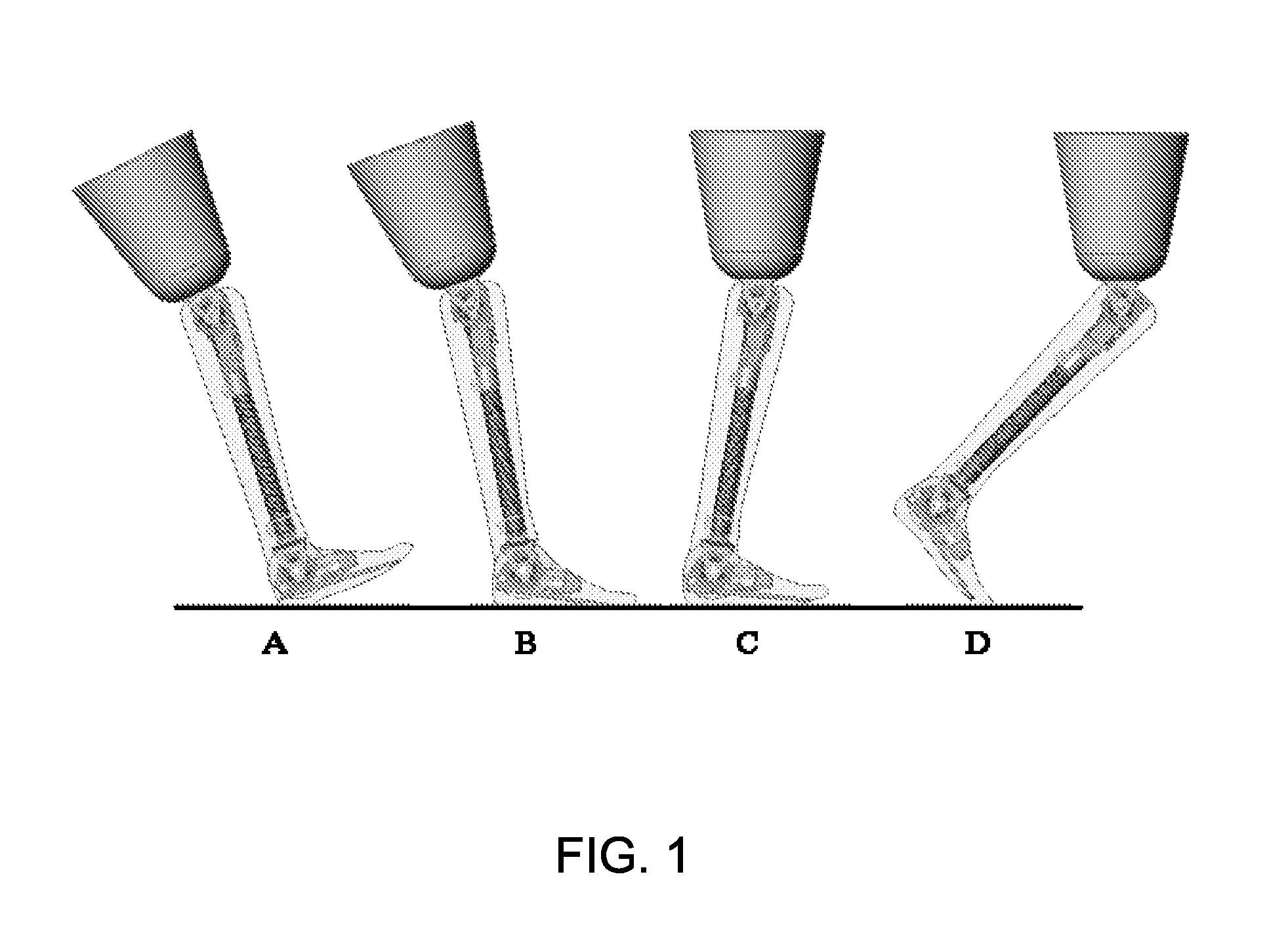
If the foot is not dorsi-flexed during the swing phase, it would most likely catch on the walking surface and cause the person to stumble and fall, which may lead to serious injury.
If the dynamic response is too stiff, the foot bounces back too quickly.
If the spring is too soft, it stores less energy and releases too late.

Method used


Image

  • Energy storing foot plate
  • Energy storing foot plate
  • Energy storing foot plate

Examples


Embodiment Construction

[0017]Before the present invention is disclosed and described, it is to be understood that this invention is not limited to the particular process steps and materials disclosed herein because such process steps and materials may vary somewhat. It is also to be understood that the terminology used herein is used for the purpose of describing particular embodiments only. The terms are not intended to be limiting because the scope of the present invention is intended to be limited only by the appended claims and equivalents thereof.

[0018]It must be noted that, as used in this specification and the appended claims, the singular forms “a,”“an,” and “the” include plural referents unless the context clearly dictates otherwise.

[0019]As used herein, “substantially” or “substantial” refers to the complete or nearly complete extent or degree of an action, characteristic, property, state, structure, item, or result. For example, an object that is “substantially” enclosed would mean that the obj...


PUM


Abstract

Compositions are provided for a prosthetic ankle comprising: a joint housing having a bottom surface, a clevis coupled to the joint housing such that the clevis can rotate about the joint housing, a prosthetic coupling structure that couples the clevis to an amputee, and an articulating joint contained in the joint housing. Additionally, a portion of the bottom surface of the joint housing can be curved allowing a substrate a preset amount of flexion when coupled thereto and flexed in a concave position.

Description

CROSS-REFERENCE TO RELATED APPLICATIONS AND CLAIM OF PRIORITY[0001]This is a continuation-in-part of U.S. patent application Ser. No. 11 / 394,331 filed on Mar. 29, 2006, which is a non-provisional of U.S. provisional patent application Ser. No. 60 / 666,388, filed on Mar. 29, 2005, which are hereby incorporated by reference in their entirety.FIELD OF THE INVENTION[0002]The present invention relates generally to prosthetic devices.BACKGROUND[0003]An intact human foot, connected to its ankle, travels through stance and swing phases of a gait cycle during each stride of motion, whether the motion involves walking, jogging, or running. By adjusting the stiffness and damping characteristics of a prosthetic ankle or foot mechanism, the springiness of the intact natural human foot and its corresponding natural human joints may be mimicked, thereby optimizing the prosthetic for the desired motion of the wearer. The characteristics that are desired to store and release energy appropriately for ...

Claims


Application Information

Patent Timeline
Patent Type & Authority Applications(United States)
IPC IPC(8): A61F2/66
CPCA61F2/6607A61F2220/0033A61F2/72A61F2002/30359A61F2002/5003A61F2002/5006A61F2002/5033A61F2002/6614A61F2002/6685A61F2002/6854A61F2002/704A61F2002/741A61F2002/744A61F2002/745A61F2002/748A61F2002/7625A61F2/68A61F2/74A61F2/741A61F2/744A61F2/748
Inventor IVERSEN, EDWIN KAYSEARS, HAROLD H.DYCK, ARTHUR D.KUNZ, STEVEN R.JACOBS, JOSEPH ANTHONYLINDER, JAMES R.LINDER, MELINDASTRAZDINS, PETER K.
Owner MOTION CONTROL
Why Eureka
Eureka Blog
Learn More