Key structure

Inactive Publication Date: 2009-12-31
CHI MEI COMM SYST INC
View PDF4 Cites 11 Cited by
  • Summary
  • Abstract
  • Description
  • Claims
  • Application Information

AI Technical Summary

Problems solved by technology

However, the typical structure of the multi-co

Method used


Image

  • Key structure
  • Key structure
  • Key structure

Examples


Embodiment Construction

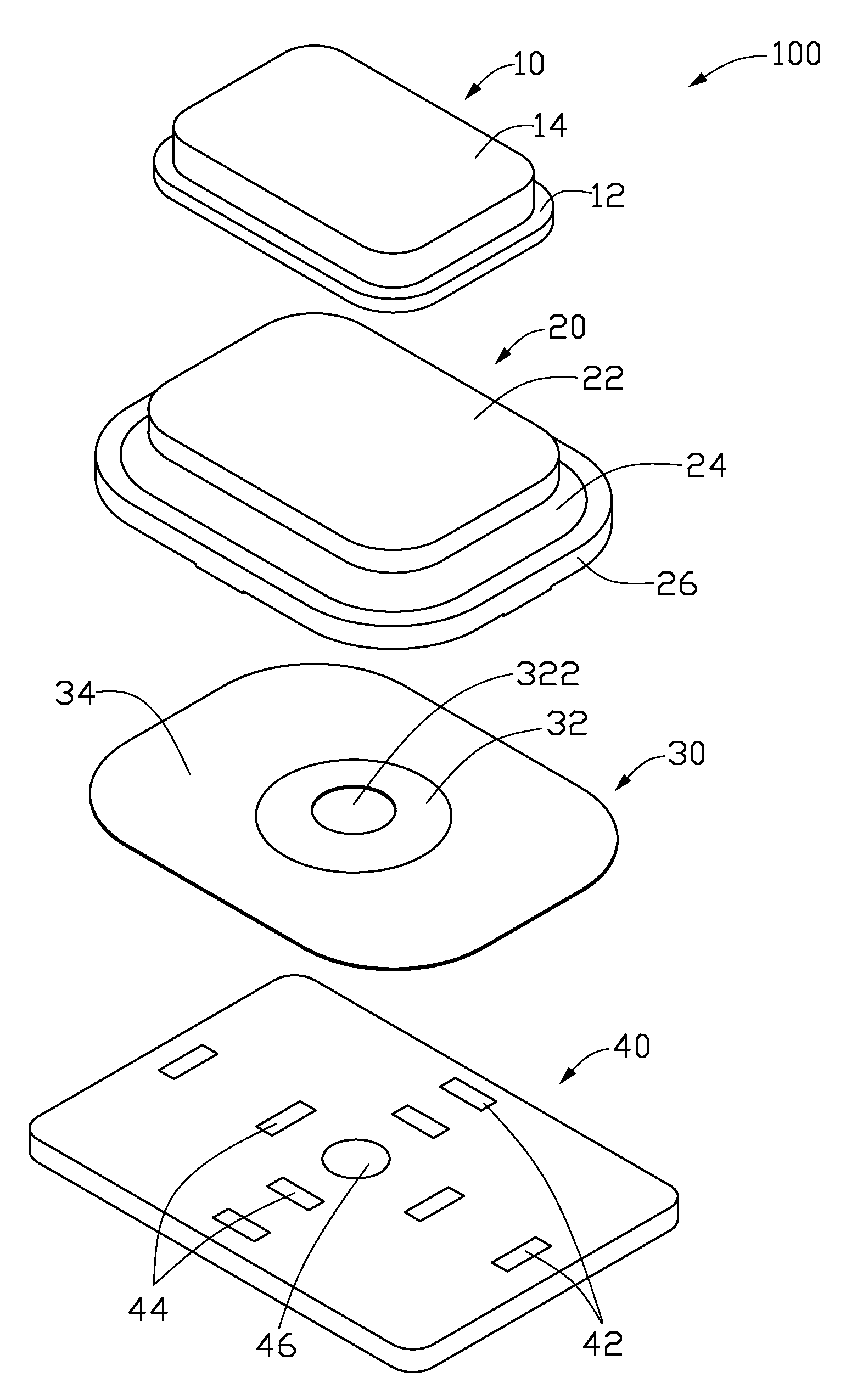
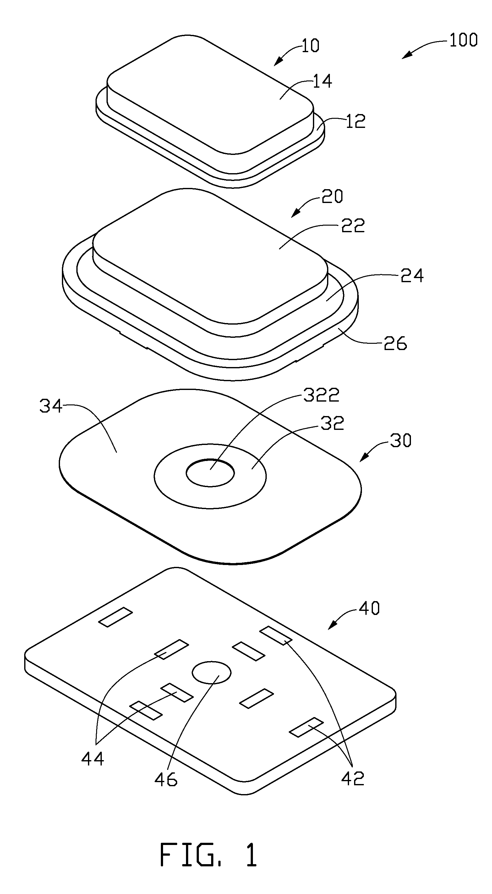
[0013]FIG. 1 shows a key structure 100, which can be used in mobile phones and other portable electronic devices, such as personal digital assistants (PDAs), digital cameras, etc. The key structure 100 includes a pressing body 10, a resilient member 20, a dome member 30 and a circuit board 40. The pressing body 10 includes a base rim 12 and a protrusion 14 protruding from the base rim 12.

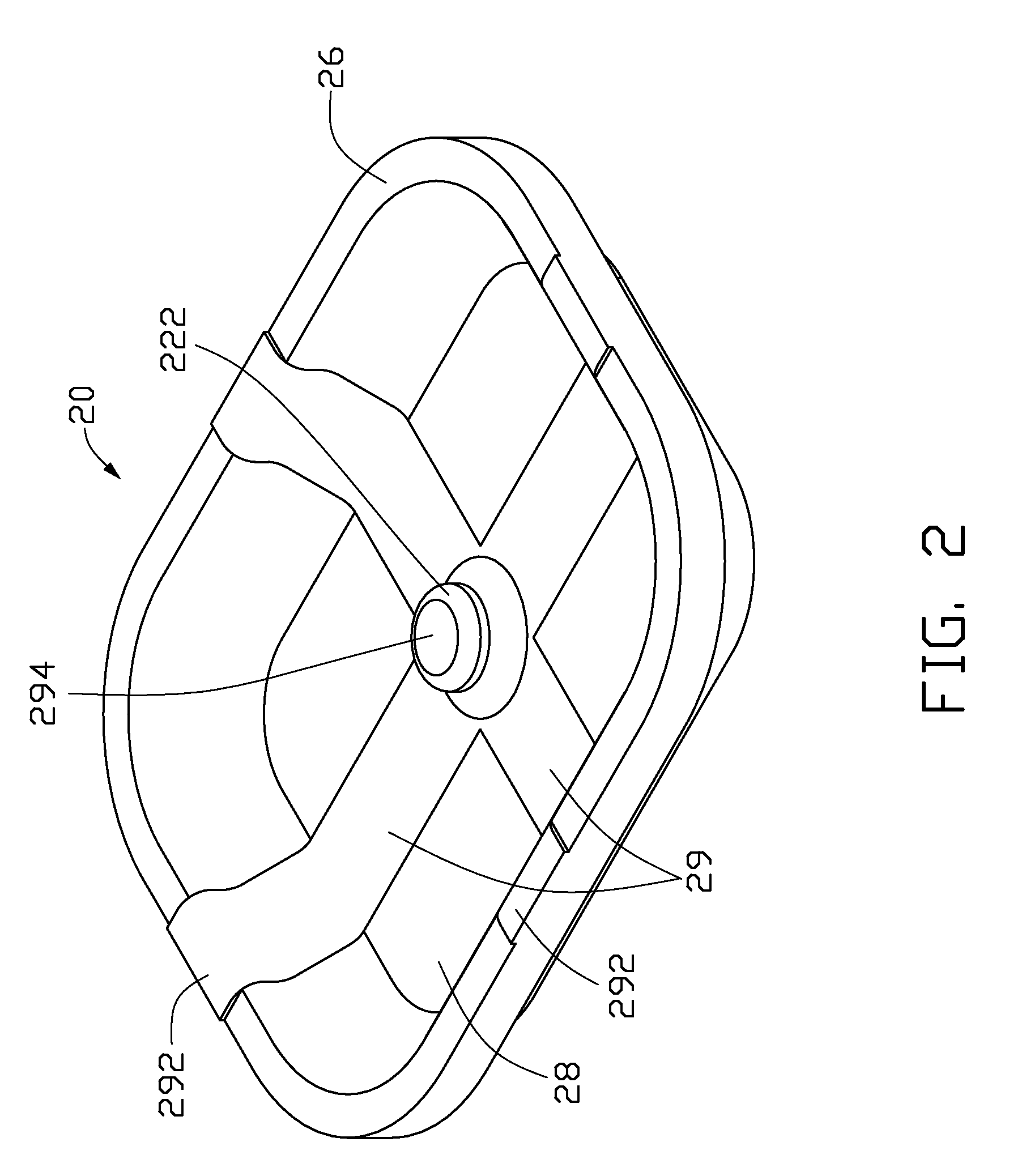
[0014]Referring further to FIG. 3, the resilient member 20 includes a cover board 22, a connecting wall 24 extending at a slant from the sidewall of the cover board 22, and a peripheral rim 26 connected to the bottom of the connecting wall 24 and substantially perpendicular to the cover board 22. The base rim 12 can receive the cover board 22 therein and engaged to each other using adhesive. The connecting wall 24 is thin and the slant relative to with the cover board 22 at an acute angle α. The angle α can be about 40 to 50 degree.

[0015]Referring to FIG. 2, the cover board 22, the connecting wall 2...


PUM


Abstract

A key structure used in a portable electronic device includes a resilient member forming a plurality of conducting films and a column, a dome member forming an arch portion and a peripheral portion, a circuit board forming a plurality of first terminals, second terminals and a third terminal. The dome member is mounted to the circuit board, the peripheral portion electronically connects to the second terminals, the resilient member covers the dome member, the conducting films conductively contact the first terminals. The resilient member is pressed to make the column resist against the arch portion, thereby the first terminals and the second terminals are both conductive, or the first terminals, the second terminals and the third terminal are all conductive.

Description

BACKGROUND[0001]1. Technical Field[0002]The present disclosure relates to key structures, particularly to a multi-contact key structure.[0003]2. Description of Related Art[0004]Portable electronic devices such as mobile phones and personal digital assistants (PDA) are widely used. Keys that can produce different results according to how they are pressed are herein called multi-contact keys. For example, a key or button of device that is pressed part way down to focus a camera then pressed all the way down to take a picture after focusing is done is one such multi-contact key.[0005]However, the typical structure of the multi-contact key is complex and not easy to assemble.[0006]Therefore, there is room for improvement within the art.BRIEF DESCRIPTION OF THE DRAWINGS[0007]Many aspects of the present key structure can be better understood with reference to the following drawings. The components in the various drawings are not necessarily drawn to scale, the emphasis instead being place...

Claims


Application Information

Patent Timeline
IPC IPC(8): H01H3/12
CPCH01H13/807H01H2205/016H01H2225/03H01H2225/002H01H2225/018H01H2215/008
Inventor CHIU, YEN-NAN
Owner CHI MEI COMM SYST INC
Why Eureka
Try Eureka