
Dehumidifier with multistage draining

a multi-stage, dehumidifier technology, applied in the direction of defrosting, heating types, domestic cooling devices, etc., can solve the problems of increasing damage to buildings, lowering efficiency, and inconvenient use of conventional dehumidifiers

Inactive Publication Date: 2010-01-07
NEW WIDETECH IND
View PDF6 Cites 24 Cited by
  • Summary
  • Abstract
  • Description
  • Claims
  • Application Information

AI Technical Summary

Benefits of technology

[0009]When an external pipe is connected to the attachment connector to actuate the switch and the condensed water in the container raises the float to actuate the float actuator, the drain motor is switched on to pump the condensed water out of the container. The dehumidifier automatically drains the condensed water in the container according to the quantity of the condensed water. Therefore, the dehumidifier does not have to be cleared frequently and is convenient.

Problems solved by technology

However, the conventional dehumidifier is inconvenient.
When the container is removed for emptying, the dehumidifier will also cease operation, lowering efficiency.
Moreover, the dehumidifier must be monitored, so when left running at night, the dehumidifier may fill and cease operation and this may increase damage to buildings or cause discomfort.

Method used


Image

  • Dehumidifier with multistage draining
  • Dehumidifier with multistage draining
  • Dehumidifier with multistage draining

Examples


Embodiment Construction

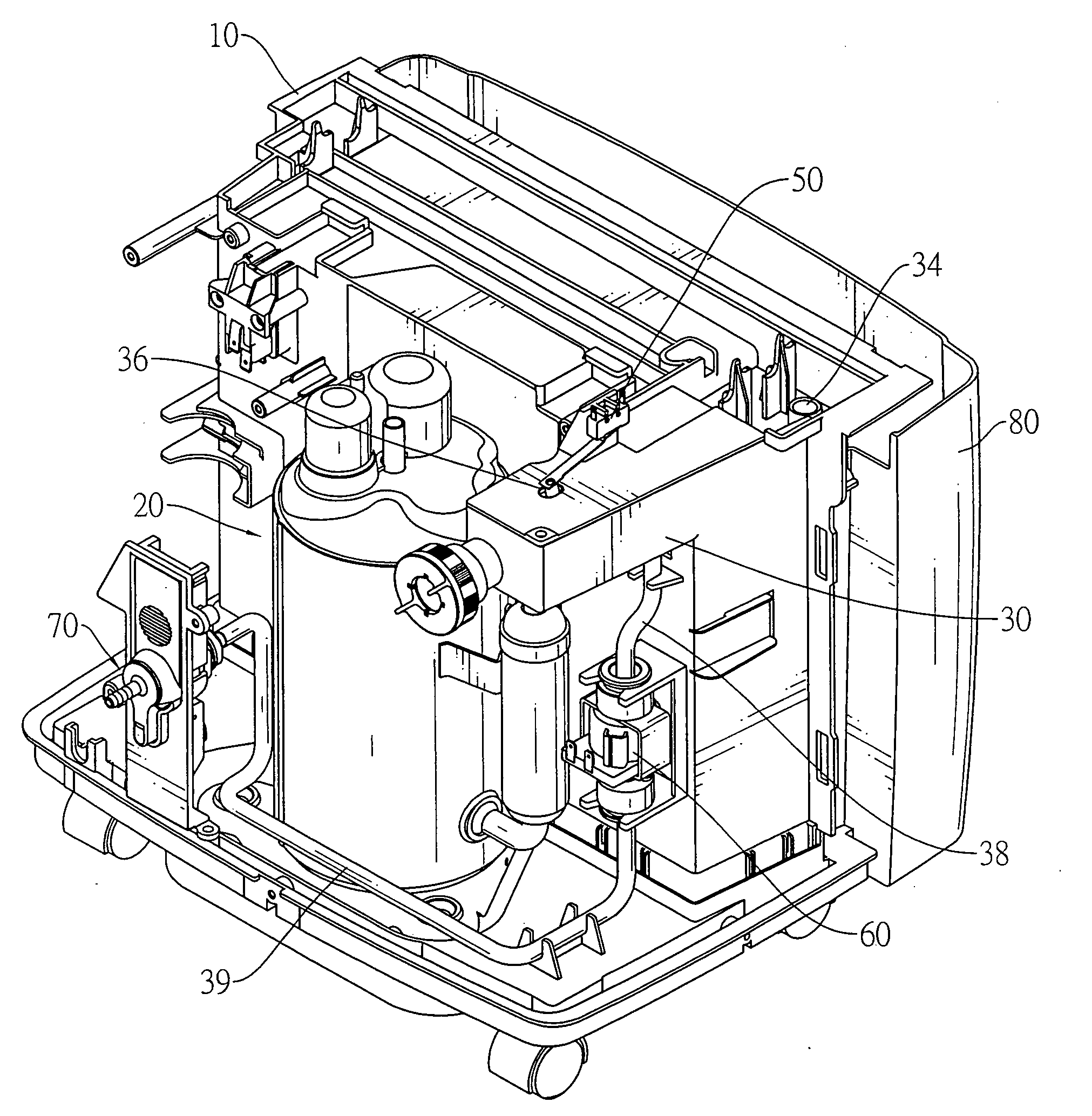
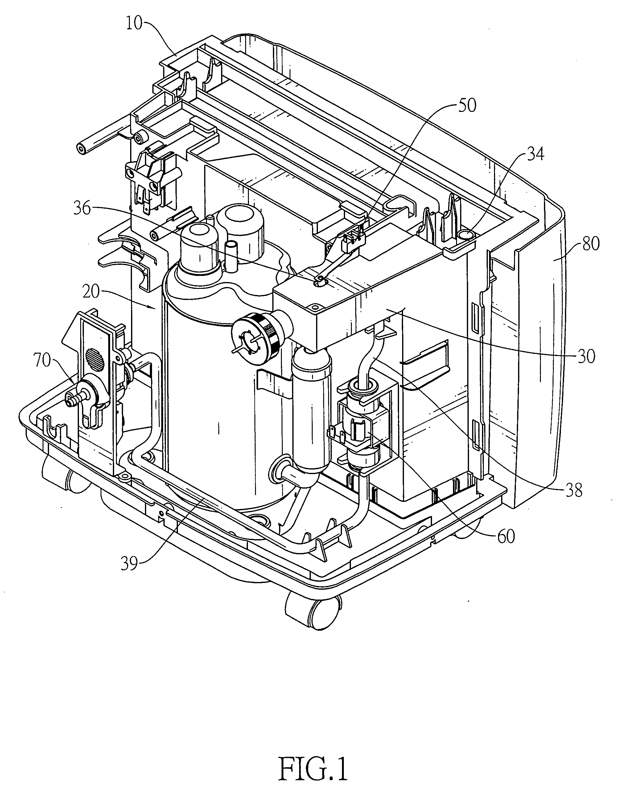
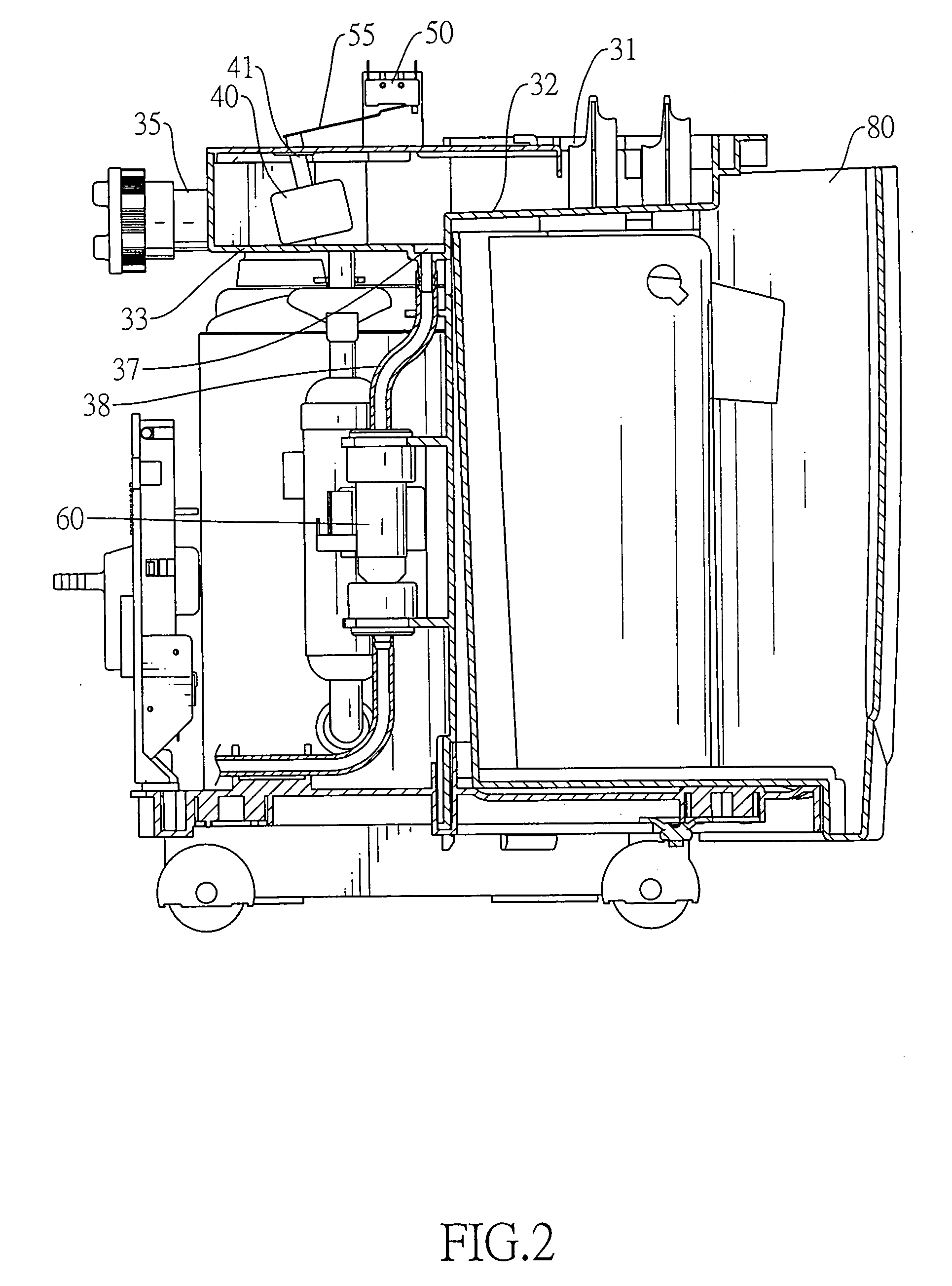
[0022]With reference to FIGS. 1 and 2, a dehumidifier with multistage draining comprises a housing (10), a dehumidifying assembly (20), a container (30), a float (40), a float actuator (50), an attachment actuator (70), a drain motor (60), a drain pipe (38), a connecting pipe (39) and a water-storage tank (80).

[0023]The dehumidifying assembly (20) is mounted in the housing (10), sucks humid air into the housing (10), cools the humid air to condense gaseous water into condensed water, thereby separating the humid air into dry air and the condensed water to dehumidify the humid air, heats and exhausts the dry air out of the housing (10), maybe using a heat exchanger and may have a compressor, a radiator, a fan and so forth as well known and described in the art. With further reference to FIGS. 3 and 4, the container (30) is mounted in the housing (10), stores the condensed water from the dehumidifying assembly (20) and has an inner end, an outer end, a top, a bottom, an opening (31), ...


PUM


Abstract

A dehumidifier with multistage draining has a container that collects and stores condensed water from a dehumidifying assembly, a float mounted in the container, a float actuator connected to the float and a drain motor connected to the float actuator and an attachment actuator having a switch. When an external pipe is connected to the attachment connector to switch on the switch and the condensed water in the container gradually raises the float to switch on the float actuator, the drain motor is switched on to pump the condensed water out of the container. The dehumidifier automatically drains condensed water in the container according to the quantity of the condensed water, does not have to be cleared frequently and is convenient.

Description

BACKGROUND OF THE INVENTION[0001]1. Field of the Invention[0002]The present invention relates to a dehumidifier, especially to a dehumidifier with multistage draining for condensing gaseous water in the air into condensed water to lower humidity of the surroundings.[0003]2. Description of the Prior Arts[0004]A dehumidifier is a common electric appliance that regulates indoor humidity. The dehumidifier sucks and cools humid air to condense gaseous water in the humid air into condensed water and therefore to separate the humid air into dry air and condensed water. Then the dehumidifier heats and exhausts the dry air out of the dehumidifier. Therefore the humidity of the surroundings is lowered and the surroundings become comfortable. Dehumidifiers may also be implemented to protect buildings to dry out walls after flooding or the like.[0005]A conventional dehumidifier has a container that stores condensed water. When the container is filled with condensed water, the conventional dehum...

Claims


Application Information

Patent Timeline
IPC IPC(8): F25D21/00
CPCF24F1/025F24F13/222F24F3/14F24F1/022F24F1/04Y10T137/7323
Inventor CHIU, MING-TSUNG
Owner NEW WIDETECH IND
Learn More