Surface mount magnetic components and methods of manufacturing the same

Inactive Publication Date: 2010-01-14
EATON INTELLIGENT POWER LIMITED
View PDF8 Cites 54 Cited by
  • Summary
  • Abstract
  • Description
  • Claims
  • Application Information

AI Technical Summary

Benefits of technology

[0004]With advancements in electronic packaging, the manufacture of smaller, yet more powerful, electronic devices has become possible. To reduce an overall size of such devices, electronic components used to manufacture them have become increasingly miniaturized. Manufacturing electronic components to meet such requirements presents many difficulties, thereby making manufacturing processes more expensive, and undesirably increasing the cost of the electronic components.
[0005]Manufacturing processes fo

Problems solved by technology

Especially for small core pieces, winding the coil in a cost effective and reliable manner is challenging.
Hand wound components tend to be inconsistent in their performance.
The shape of the core pieces renders them quite fragile and prone to core cracking as the coil is wound, and variation in the gaps between the core pieces can produce undesirable variation in component performance.
A further difficulty is that the DC resistance (“DCR”) may undesirably vary due to uneven winding and tension during the winding process.
The manufacture of transformer components presents similar challenges as inductor components.
For increasingly miniaturized components, providing physically gapped cores is challenging.
Establishing and maintaining consistent gap sizes is difficult to reliably accomplish in a cost effective manner.
A number of practical issues are also presented with regard to making the electrical connection between the coils and the terminal clips in miniaturized, surface mount magnetic components.
A rather fragile connection between the coil and terminal clips is typically made external to the core and is consequently vulnerable to separation.
This has proven tedious, however, from a manufacturing perspective and easier and quicker termination solutions would be desirable.
Additionally, wrapping of the coil ends is not practical for certain types of coils, such as coils having rectangular cross section with flat surfaces that are not as flexible as thin, round wire constructions.
The larger the wire gauge,

Method used


Image

  • Surface mount magnetic components and methods of manufacturing the same
  • Surface mount magnetic components and methods of manufacturing the same
  • Surface mount magnetic components and methods of manufacturing the same

Examples


Example

[0029]Exemplary embodiments of inventive electronic component designs are described herein that overcome numerous difficulties in the art. To understand the invention to its fullest extent, the following disclosure is presented in different segments or parts, wherein Part I discusses particular problems and difficulties, and Part II describes exemplary component constructions and assemblies for overcoming such problems.

I. INTRODUCTION TO THE INVENTION

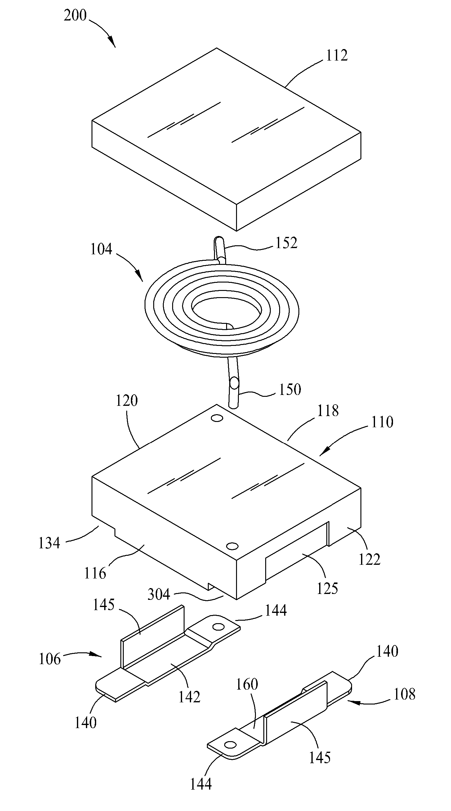
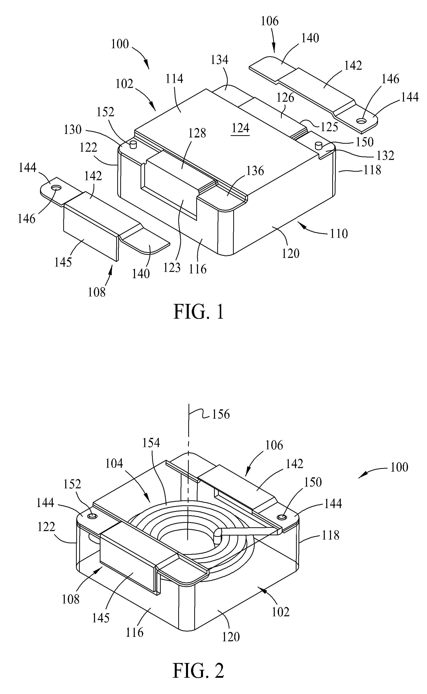
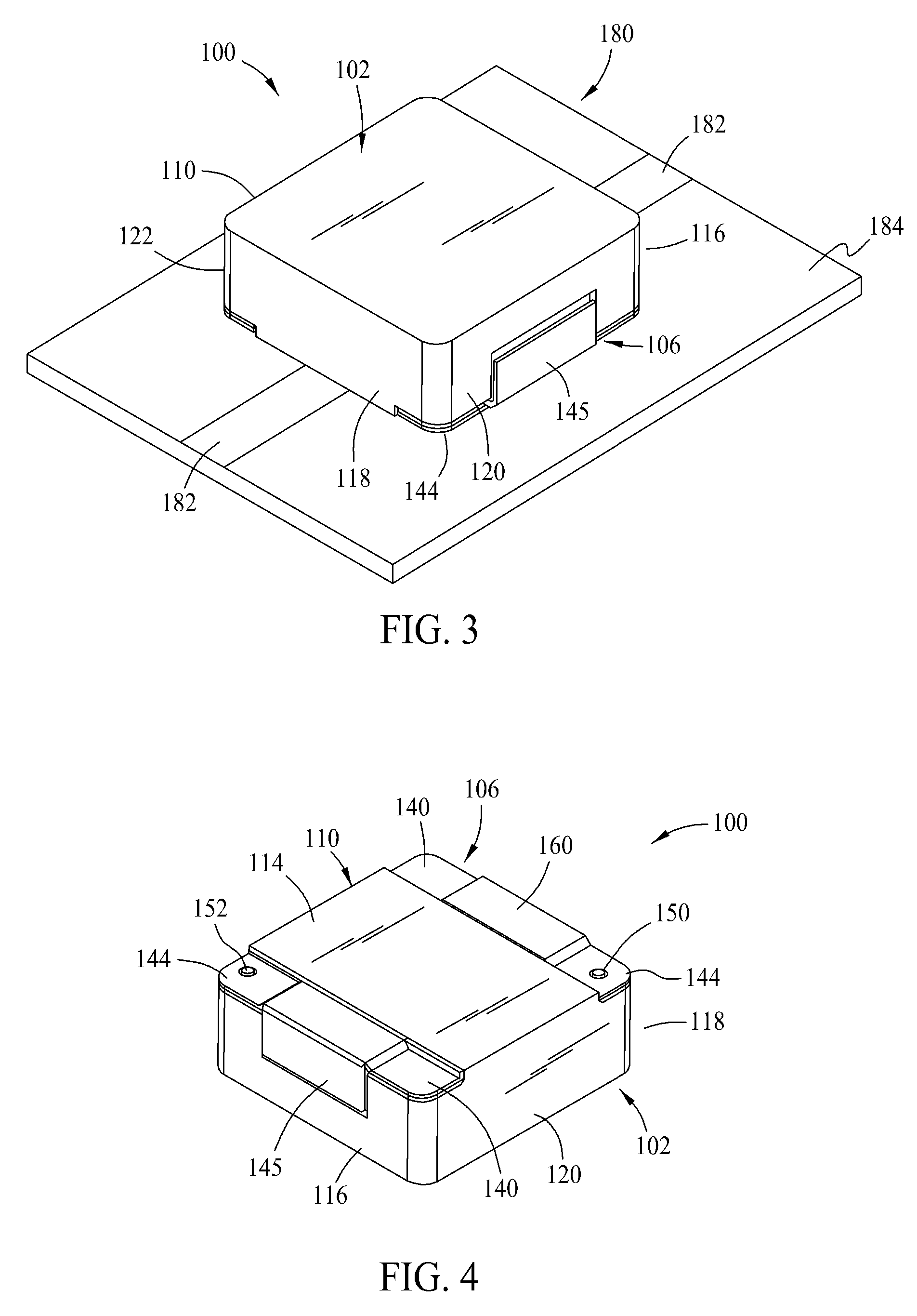
[0030]Conventional magnetic components such as inductors for circuit board applications typically include a magnetic core and a conductive winding, sometimes referred to as a coil, within the core. The core may be fabricated from discrete core pieces fabricated from magnetic material with the winding placed between the core pieces. Various shapes and types of core pieces and assemblies are familiar to those in the art, including but not necessarily limited to U core and I core assemblies, ER core and I core assemblies, ER core and ER co...


PUM

PropertyMeasurementUnit
Angleaaaaaaaaaa
Moldableaaaaaaaaaa
Electrical conductoraaaaaaaaaa

Abstract

Magnetic component assemblies including moldable magnetic materials including surface mount termination features, as well as manufacturing methods therefor, are disclosed that are advantageously utilized in providing surface mount magnetic components such as inductors and transformers.

Description

CROSS REFERENCE TO RELATED APPLICATIONS[0001]This applications claims the benefit of U.S. Provisional Application Ser. Nos. 61 / 175,269 filed May 4, 2009 and 61 / 080,115 filed Jul. 11, 2008, and is a continuation in part application of U.S. application Ser. No. 12 / 429,856 filed Apr. 24, 2009, the disclosures of which are hereby incorporated by reference in their entirety.[0002]The present application also relates to subject matter disclosed in the following commonly owned and co-pending patent applications: U.S. patent application Ser. No. 12 / 247,281 filed on Oct. 8, 2008 and entitled “High Current Amorphous Powder Core Inductor”; U.S. patent Ser. No. 12 / 181,436 filed Jul. 29, 2008 and entitled “A Magnetic Electrical Device”; U.S. Provisional Patent Application No. 61 / 080,115 filed Jul. 11, 2008 and entitled “High Performance High Current Power Inductor”, and U.S. patent application Ser. No. 12 / 138,792 filed Jun. 13, 2008 and entitled “Miniature Shielded Magnetic Component”; and U.S. ...

Claims


Application Information

Patent Timeline
IPC IPC(8): H01F27/02H01F41/00
CPCH01F27/027H01F27/263Y10T29/4902H01F41/04H01F27/292
Inventor YAN, YIPENGBOGERT, ROBERT JAMES
Owner EATON INTELLIGENT POWER LIMITED
Why Eureka
Try Eureka