Nitric oxide reactor and distributor apparatus and method

a technology of nitric oxide and distributor apparatus, which is applied in the direction of process and machine control, separation processes, instruments, etc., can solve the problems of insufficient inability to inhibit the widespread use of such therapies, and high cost of nitric oxide introduction to the human body. , to achieve the effect of convenient removal

a technology of nitric oxide and distributor apparatus, which is applied in the direction of process and machine control, separation processes, instruments, etc., can solve the problems of insufficient inability to inhibit the widespread use of such therapies, and high cost of nitric oxide introduction to the human body. , to achieve the effect of convenient removal

US20100018526A1Active Publication Date: 2010-01-28SYK TECH LLC

Image

  • Nitric oxide reactor and distributor apparatus and method
  • Nitric oxide reactor and distributor apparatus and method
  • Nitric oxide reactor and distributor apparatus and method

Examples


embodiment b

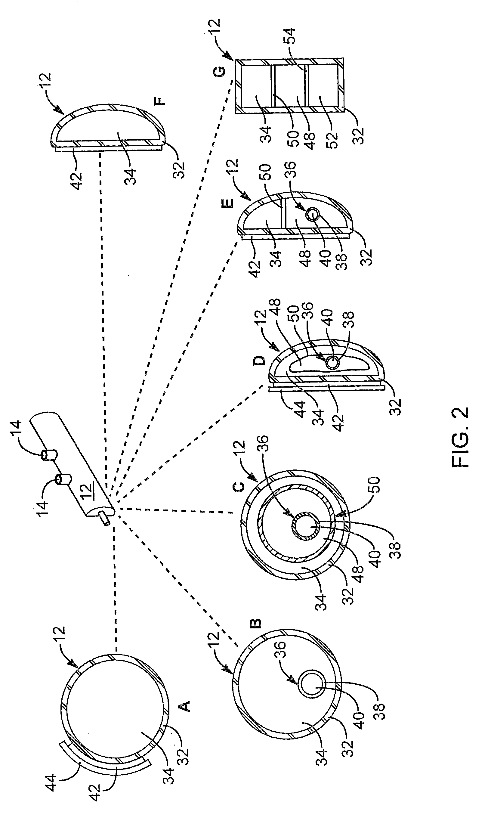
[0031 of FIG. 2 includes an additional chamber 40 separated by a wall 36. In this embodiments, one reactant may occupy the principal chamber 34, while a second reactant occupies the chamber 40 within the wall 36. If the wall 36 is formed of glass, then bending the distributor 12 may fracture the wall 36, exposing the reactants in the chamber 34 to the reactants in the chamber 40. Accordingly, the relative sizes of the chambers 34, 40 may be configured according to the necessary and appropriate quantities of the reactants contained therein, respectively.

[0032]The reactants in the chambers 34, 40 may be dry, wet, or one may be dry and one may be wet. Likewise, one chamber 34, 40 may contain both reactive ingredients mixed together but completely dry, while the other chamber 40, 34 contains a liquid capable of acting as a transport medium and thus activating the reaction between the dry ingredients.

[0033]Substantially all the illustrated embodiments for a reactor 20 or for a distributo...


PUM


Abstract

A reaction and distribution system may include a distributor securable near or in a path correspond to a breathing passage such as the nostrils or the mouth of a user for delivering nitric oxide therapy thereto. The distributor may contain an internal reactor for creating the nitric oxide from reactants. Alternative embodiments may rely on a line delivering nitric oxide to the distributor from a remote generator such as a cannister carried in a pocket or placed / at the bedside of a user.

Description

RELATED APPLICATIONS[0001]This application claims the benefit of co-pending U.S. Provisional Patent Application Ser. No. 61 / 025,230, filed on Jan. 31, 2008.BACKGROUND[0002]1. The Field of the Invention[0003]This invention relates to treatments providing nitric oxide as a vasodilator, and, more particularly, to generation and delivery of gaseous nitric oxide for inhaling.[0004]2. Background[0005]The discovery of the nitric oxide effect in live tissues garnered a Nobel prize. Much of the work in determining the mechanisms for implementing and the effects of nitric oxide administration are reported in literature including papers, advertising, catalogs, and patents. Much of the work deals with introduction of substances that provide a nitric oxide effect in the body. Still other applications may involve topical preparations introducing nitric oxide. Still other applications rely on bottled nitric oxide gas. Introduction of nitric oxide to the human body has traditionally been expensive....

Claims


Application Information

Patent Timeline
28 Jan 2010
Publication
US20100018526A1
IPC
A61M16/10
CPC
A61M16/0666; A61M2202/0275; A61M16/10; B01D2257/404; C01B21/24; B01D53/22; A61M16/06; A61M2209/06
Inventors
MILLER, RANDY J.; JONES, CHRISTIE M.