Dispenser head and receptacle fitted therewith

a dispenser head and receptacle technology, applied in the direction of single-unit apparatus, lighting and heating apparatus, combustion types, etc., can solve the problems of relatively complex dispenser head and unsuitable dispenser head for dispensing substances, and achieve the effect of simple structur

Inactive Publication Date: 2001-07-10
LOREAL SA
View PDF9 Cites 71 Cited by
  • Summary
  • Abstract
  • Description
  • Claims
  • Application Information

AI Technical Summary

Benefits of technology

An object of the present invention is to provide a novel spray head for fixing on a control rod of a valve or a pump, which is of re

Problems solved by technology

Such dispenser heads are not suitable for dispensing a substance that is liable to fo

Method used


Image

  • Dispenser head and receptacle fitted therewith
  • Dispenser head and receptacle fitted therewith
  • Dispenser head and receptacle fitted therewith

Examples


Embodiment Construction

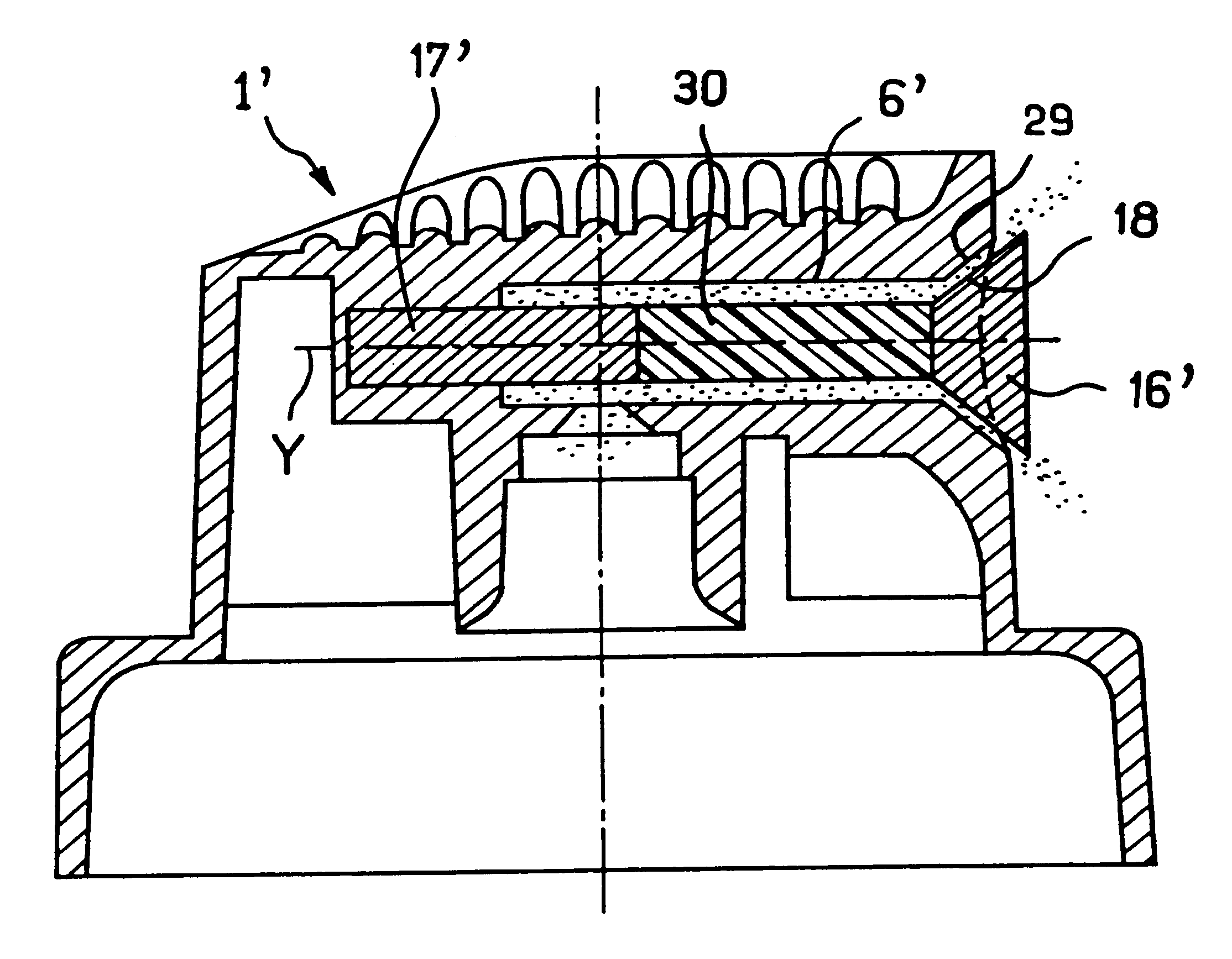
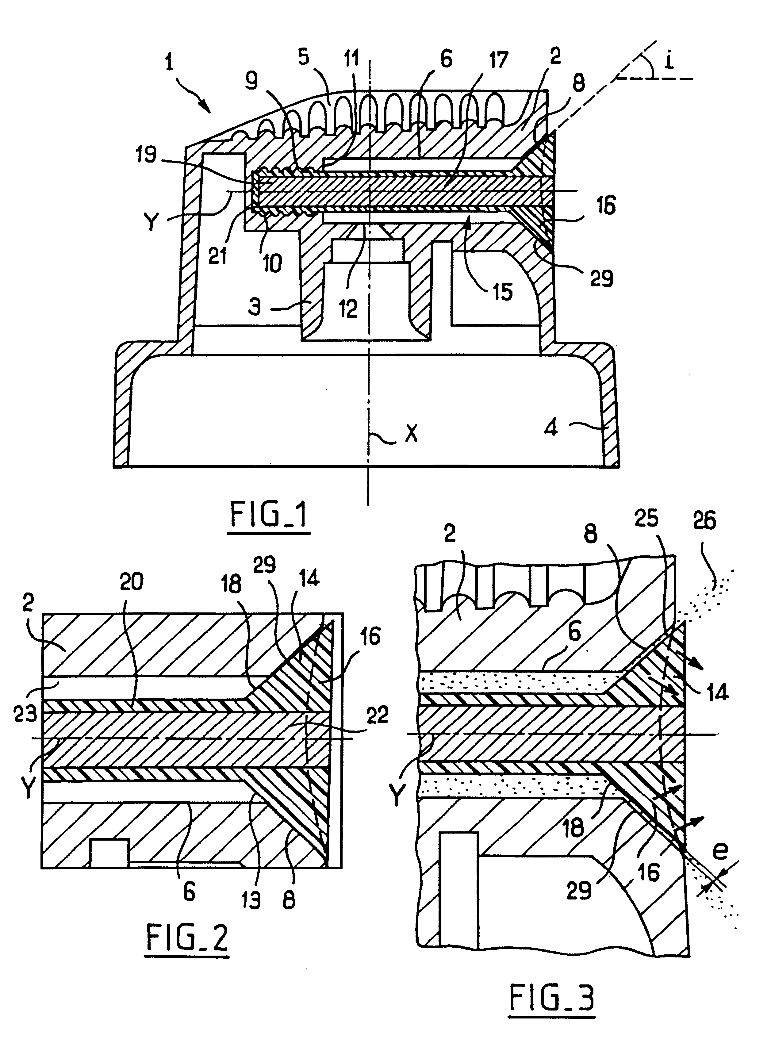
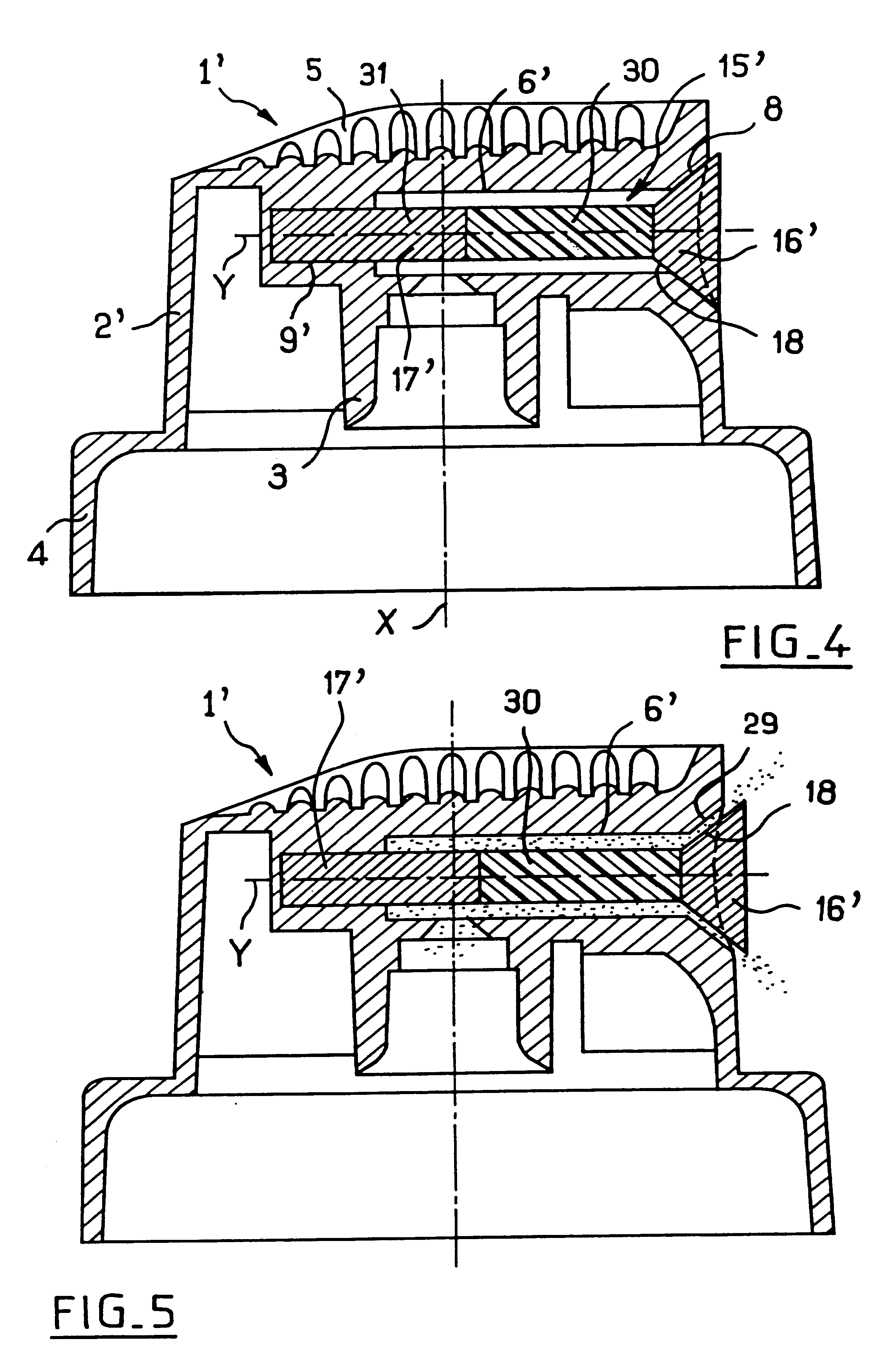
The dispenser head 1 shown in FIG. 1 comprises a body 2 having an endpiece 3 for engagement on the control rod of a valve or a pump (not shown) fitted to a receptacle containing a liquid that is to be sprayed, for example a hair spray.

The bottom portion of the body 2 comprises a tubular skirt 4 for improving the appearance of the receptacle fitted with the dispenser head 1.

The endpiece 3 is circularly symmetrical about an axis X.

The dispenser head 1 has a depression 5 in its top face constituting a bearing surface for the finger of the user pressing down the dispenser head 1 to spray the substance.

The body 2 has a housing 6 on an axis Y that is perpendicular to the axis X.

This housing 6 opens out in the front face of the body 2 via an outwardly-diverging conical mouth 8.

The endpiece 3 communicates with the housing 6 via an orifice 12.

At its end opposite from its mouth 8, the housing 6 has a shoulder 11 defining the front end of a setback 9 provided with a succession of corrugations ...


PUM


Abstract

A spray head for fixing on a control rod of a valve or a pump. The spray head includes a body and a shutter disposed in a housing of the body. The housing is suitable for dispensing substance under pressure. At rest the shutter is in a closed position in which its frustoconical head portion is seated a frustoconical bearing surface of the body. The shutter moves away from the bearing surface under the pressure of the substance contained in the housing when the substance is being dispensed to form an annular dispenser orifice enabling the substance to be dispensed in the form of a hollow conical spray, at least in the vicinity of the spray head. The shutter moves away from the bearing surface against a resilient return action urging it back towards its closed position and returns to the closed position when the pressure of the substance diminishes.

Description

Dispenser heads are known in which the dispenser orifice is permanently open.Such dispenser heads are not suitable for dispensing a substance that is liable to form a solid residue on drying out.Proposals have therefore been made for dispenser heads in which the dispenser orifice is closed except during periods of use, so as to prevent the substance from drying out inside it.In particular, U.S. Pat. No. 3,250,474 discloses a dispenser head having a nozzle that is capable of being displaced relative to the body of the dispenser head. The body has a pin arranged to engage in the dispenser orifice during periods of non-use.Such a dispenser head is relatively complex to make.In addition, for reasons of mechanical strength, the diameter of the pin must not be made too small, so the dispenser orifice needs to have a diameter that is relatively large, thereby preventing the substance being dispensed at a low flow rate.OBJECTS AND SUMMARY OF THE INVENTIONAn object of the present invention i...

Claims


Application Information

Patent Timeline
IPC IPC(8): B05B1/28B05B1/30B05B11/00B05B1/32B65D47/04B65D47/20F16K15/14B65D83/40B05B1/34B05B9/04
CPCB05B1/06B05B1/28B05B1/323B05B11/0064F16K15/148B05B11/0072B65D47/2075B65D83/205B05B11/007Y10T137/7879Y10T137/7924Y10T137/7931F16K15/026
Inventor BAUDIN, GILLES
Owner LOREAL SA
Why Eureka
Try Eureka