Speed-ratio control apparatus for vehicular continuously variable transmission

a control apparatus and continuously variable technology, applied in the direction of gearing control, gearing elements, gearing, etc., can solve the problem of the risk of deterioration of driving comfort felt by the vehicle operator, and achieve the effect of slow acceleration of the vehicle and high ra

Inactive Publication Date: 2007-05-03
TOYOTA JIDOSHA KK
View PDF4 Cites 73 Cited by
  • Summary
  • Abstract
  • Description
  • Claims
  • Application Information

AI Technical Summary

Benefits of technology

[0011] According to a first preferred form of the speed-ratio control apparatus of this invention, the target-input-speed setting portion gradually increases the second transient target input speed toward the first transient target input speed along a curve of a first-order time lag. In this form of this invention, the second transient target input speed which is initially close to the actual input shaft speed is gradually increased back toward the first transient target value along the curve of the first-order time lag, so that the speed ratio of the continuously variable transmission is changed at a relatively low rate suitable for relatively slow acceleration of the vehicle while preventing a shifting shock or a delayed shifting of the continuously variable transmission, in the second portion of the rapid shifting period following the first portion in which the speed ratio is changed at a relatively high rate.
[0012] In one advantageous arrangement of the above-described first preferred form of the invention, the second transient target input speed NIN*P2 defined by the curve of the first-order time lag is represented by an equation NIN*P2(t)=1×ε−t / T, wherein “T” is a time constant which decreases with an increase of a rate of increase of an amount of operation of said vehicle accelerating member. In this arrangement, the rate of change of the speed ratio of the continuously variable transmission in the second portion of the rapid shifting period increases with an increase of the degree of requirement for acceleration of the vehicle as a result of an operation of the vehicle accelerating member by the vehicle operator, so that the vehicle operator's requirement regarding the vehicle acceleration can be more adequately reflected on the rate of change of the speed ratio of the continuously variable transmission.
[0013] According to a second preferred form of this invention, the target-input-speed setting portion determines the first transient target input speed on the basis of an amount of operation of the vehicle accelerating member and a running speed of the vehicle. In the present form of the invention, the vehicle operator's desire regarding the vehicle acceleration can be more adequately reflected on the rate of change of the speed ratio of the continuously variable transmission.

Problems solved by technology

Where the acceleration value of the vehicle as desired by the vehicle operator is not so high, the stepping increase of the transient target input speed which results in the rapid acceleration of the vehicle unfavorably has a risk of deterioration of driving comfort as felt by the vehicle operator.

Method used


Image

  • Speed-ratio control apparatus for vehicular continuously variable transmission
  • Speed-ratio control apparatus for vehicular continuously variable transmission
  • Speed-ratio control apparatus for vehicular continuously variable transmission

Examples


Embodiment Construction

[0030] The preferred embodiments of this invention will be described in detail, by reference to the accompanying drawings.

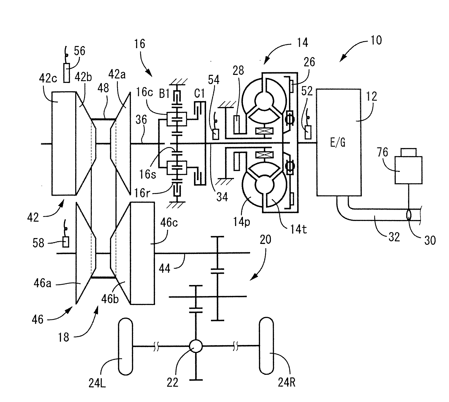
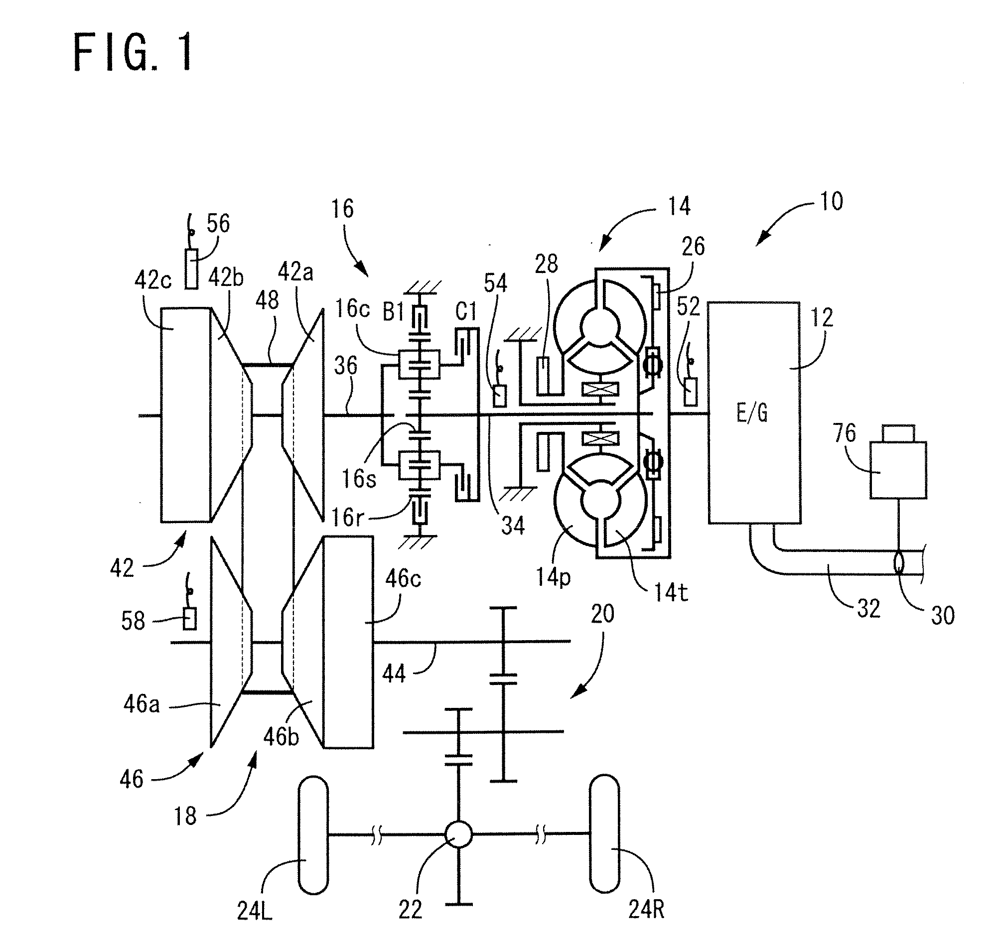
[0031] Referring first to the schematic view of FIG. 1, there is illustrated a vehicular drive system 10 including a continuously variable transmission (CVT) 18 of a belt-and-pulley type which is controlled by a speed-ratio control apparatus constructed according to one embodiment of this invention. The vehicular drive system 10 is of a transversely installed type suitably used on an FF vehicle (front-engine front-drive vehicle), and includes a drive power source in the form of an internal combustion engine 12. An output of the engine 12 is transmitted to right and left drive wheels 24R, 24L of a motor vehicle through a crankshaft of the engine 12, a fluid-operated power transmitting device in the form of a torque converter 14, a forward / reverse switching device 16, the above-indicated continuously variable transmission 18, a reduction gear device 20 and a diffe...


PUM


Abstract

A speed-ratio control apparatus for controlling a speed ratio of a continuously variable transmission of a vehicle, such that an actual input speed of the transmission coincides with a target input speed, the apparatus including an acceleration-requirement determining portion operable to determine whether non-rapid acceleration or rapid acceleration of the vehicle is required by a vehicle operator, and a target-input-speed setting portion operable, upon determination of the operator's requirement for the non-rapid acceleration, to implement an instantaneous stepping increase of the target input speed to a first transient target value, (ii) hold the target input speed at the first transient target value in a first portion of a rapid shifting period, (iii) instantaneously reduce, at the end of the first portion of the rapid shifting period, the target input speed to an initial value of a second transient target value which initial value is close to the actual input speed and lower than the first transient target value, and (iv) gradually increase, in a second portion of the rapid shifting period, the target input speed back toward the first transient value, and upon determination of the operator's requirement for the rapid acceleration, the target-input-speed setting portion holding the target input speed at the first transient target input speed during the rapid shifting period, without setting at the second transient target value.

Description

[0001] This application is based on Japanese Patent Application No. 2005-317478 filed Oct. 31, 2005, the contents of which are incorporated hereinto by reference. BACKGROUND OF THE INVENTION [0002] 1. Field of the Invention [0003] The present invention relates in general to a speed-ratio control apparatus arranged to control a speed ratio of a vehicular continuously variable transmission such that an actual value of an input speed of the transmission coincide with a target value of the input speed, and more particularly to setting of the target input speed value upon requirement for acceleration of a vehicle. [0004] 2. Discussion of Related Art [0005] For a continuously variable transmission provided on a motor vehicle, there is known a speed-ratio control apparatus arranged to control the speed ratio of the continuously variable transmission such that an actual value of the input speed of the transmission coincides with a target value of the input speed, which is set on the basis o...

Claims


Application Information

Patent Timeline
Patent Type & Authority Applications(United States)
IPC IPC(8): F16H61/662F16H9/00F16H59/18F16H59/44F16H59/48F16H61/02F16H61/24F16H61/66
CPCF16H61/66259Y10T477/6237Y10T477/6242
Inventor MATSUI, YASUNARITAMURA, TADASHI
Owner TOYOTA JIDOSHA KK
Why Eureka
Try Eureka