Wheel creep control of hydraulic hybrid vehicle using regenerative braking

a technology of hydraulic hybrid vehicles and regenerative braking, which is applied in the direction of fluid couplings, couplings, transportation and packaging, etc., can solve the problems of insufficient braking capacity of friction brakes at the expected brake pedal position, and the driver may have to exert an uncomfortable level of force, so as to prevent vehicle creep, slow down the acceleration of the vehicle, and prevent unfavorable pumping

Inactive Publication Date: 2006-12-12
FORD GLOBAL TECH LLC
View PDF18 Cites 35 Cited by
  • Summary
  • Abstract
  • Description
  • Claims
  • Application Information

AI Technical Summary

Benefits of technology

[0006]To overcome this difficulty, the displacement of the hydraulic pump / motor is increased to require slightly more torque than the torque produced by an idling engine driving a torque converter of an automatic transmission. This will prevent vehicle creep, the slow acceleration of the vehicle due to torque transmitted from the engine through the torque converter and automatic transmission, on a flat surface with minimal brake pedal effort. If the vehicle is on a hill or for some other reason begins to roll despite the pump / motor operating a maximum displacement, the volumetric displacement of the pump / motor is returned to zero, and the driver must resort to pressing harder on the brake pedal to prevent undesired pumping. If pressure in the high pressure accumulator is low, then a small amount of pumping under these conditions may be allowed.
[0007]Using regenerative braking energy for vehicle acceleration can provide a significant fuel economy benefit without the complications of repetitive engine starting and stopping or cruise load leveling. Since HPA can provide this fuel economy benefit without significant changes to the conventional powertrain, it is possible to achieve the fuel economy benefit without adversely affecting vehicle performance.

Problems solved by technology

When the vehicle speed is too slow for regenerative braking to be effective, the friction brakes may have insufficient braking capacity at the expected brake pedal position.
Then the driver may have to exert an uncomfortable level of force on the brake pedal to produce the level of friction braking desired.

Method used


Image

  • Wheel creep control of hydraulic hybrid vehicle using regenerative braking
  • Wheel creep control of hydraulic hybrid vehicle using regenerative braking
  • Wheel creep control of hydraulic hybrid vehicle using regenerative braking

Examples


Embodiment Construction

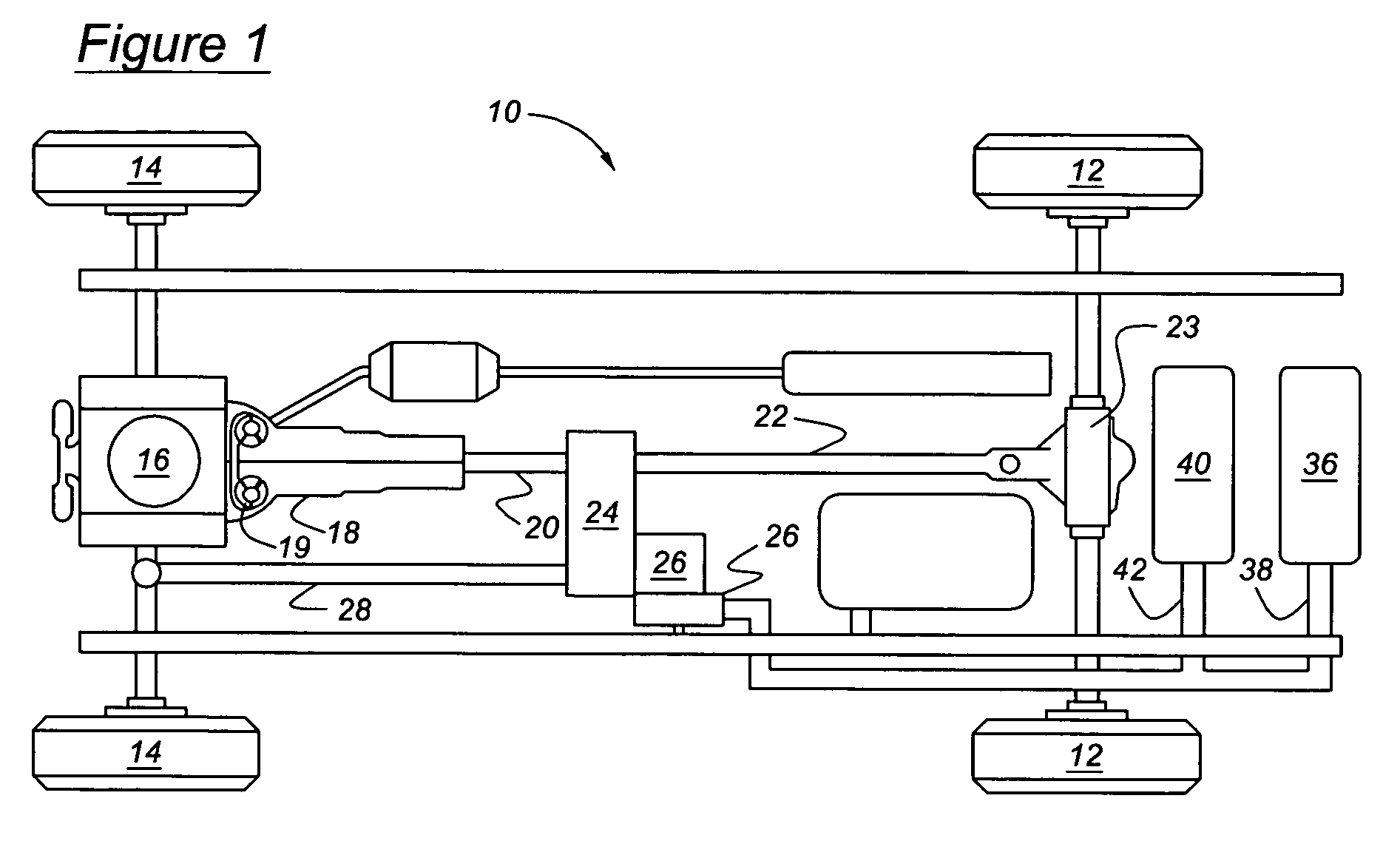
[0015]Referring now to the drawings, there is illustrated in FIG. 1 a hydraulic hybrid powertrain 10 for driving the rear wheels 12 and front wheels 14 of a motor vehicle. A power source 16, such as an internal combustion engine, is driveably connected to a transmission 18, preferably an automatic transmission that produces multiple ratios of the speed of the engine and the speed of an output shaft 20. Suitable alternative transmissions include those that are manually operated, and those that produce continuously variable speed ratios or infinitely variable speed ratios, having chain drive, belt drive or traction drive mechanisms. The transmission output shaft 20 is continually driveably connected to the rear wheels 12 through a rear driveshaft 22, rear axle shafts, and a rear differential mechanism. A transfer case 24 selectively transfers a portion of the torque carried by output shaft 20 to a front driveshaft 28, which is driveably connected to the front wheels 14 through a front...


PUM


Abstract

A system according to this invention opposes creep in a hydraulic hybrid motor vehicle. An accumulator contains fluid at high pressure, and a reservoir contains fluid at lower pressure. An engine produces positive torque at the wheels during an engine idle condition, and a pump / motor, driveably connected to the wheels and the engine, has a variable volumetric displacement pumps fluid to the accumulator from the reservoir. A control system determines a magnitude of negative torque transmitted from the wheels to the pump / motor that would exceed the magnitude of positive torque, determines the volumetric displacement of the pump / motor corresponding to the magnitude of negative torque, changes the displacement of the pump / motor to the required displacement, and operates the pump / motor as a pump driven by negative torque from the wheels to pump fluid from the reservoir to the accumulator.

Description

BACKGROUND OF THE INVENTION[0001]The invention relates to a hybrid vehicle drive system having a primary power source, such as a conventional internal combustion engine, and another power source, such as an accumulator containing high pressure fluid. More particularly, the invention pertains to vehicle hill holding using a hydraulic drive system.[0002]Hydraulic Power Assist (HPA) is a type of hydraulic hybrid vehicle, in which energy from regenerative braking or from an engine is stored in a hydro-pneumatic accumulator, and the conversion between mechanical power and hydraulic power is achieved through high pressure pump / motor having a variable volumetric displacement. In an HPA system, using stored energy from regenerative braking to help accelerate the vehicle reduces the burden on the engine and reduces fuel use.[0003]Because of the high power density available with such hydraulic systems, it is possible to recover efficiently a significant portion of braking energy with an HPA s...

Claims


Application Information

Patent Timeline
Patent Type & Authority Patents(United States)
IPC IPC(8): B60K6/12B60W30/18F16H61/20F16H61/46F16H61/472
CPCB60K6/12B60W30/18063F16H61/20F16H61/472Y02T10/6208Y02T10/62
Inventor TESLAK, CHRISCARLSON, CLIFF
Owner FORD GLOBAL TECH LLC
Why Eureka
Try Eureka