Shelf for refrigeration units

a refrigeration unit and shelf technology, applied in the field of shelves or racks, can solve the problems of destroying glue, glass panel breaking, allowing the objects the shelf holds to fall,

Inactive Publication Date: 2010-02-04
SAINT-GOBAIN GLASS FRANCE
View PDF53 Cites 57 Cited by
  • Summary
  • Abstract
  • Description
  • Claims
  • Application Information

AI Technical Summary

Problems solved by technology

A major disadvantage of this type of shelf is that it is solely the glue on the brackets or tracks or rails of the curved glass panel which bears all the load applied to the shelf, including the weight of the glass panel and the objects it holds, ultimately destroying the glue with the risk of the glass panel breaking, allowing the objects the shelf holds to fall, and damaging the shelves located below.
Thus, in particular the tracks, which support the glass plate and are fastened to the refrigeration unit by rear rack bars or are supported by ribs in the side walls of the unit, do not form a solid structure.
Their connection to the glass panel is even more problematic when the panel is not flat.

Method used


Image

  • Shelf for refrigeration units
  • Shelf for refrigeration units
  • Shelf for refrigeration units

Examples


second embodiment

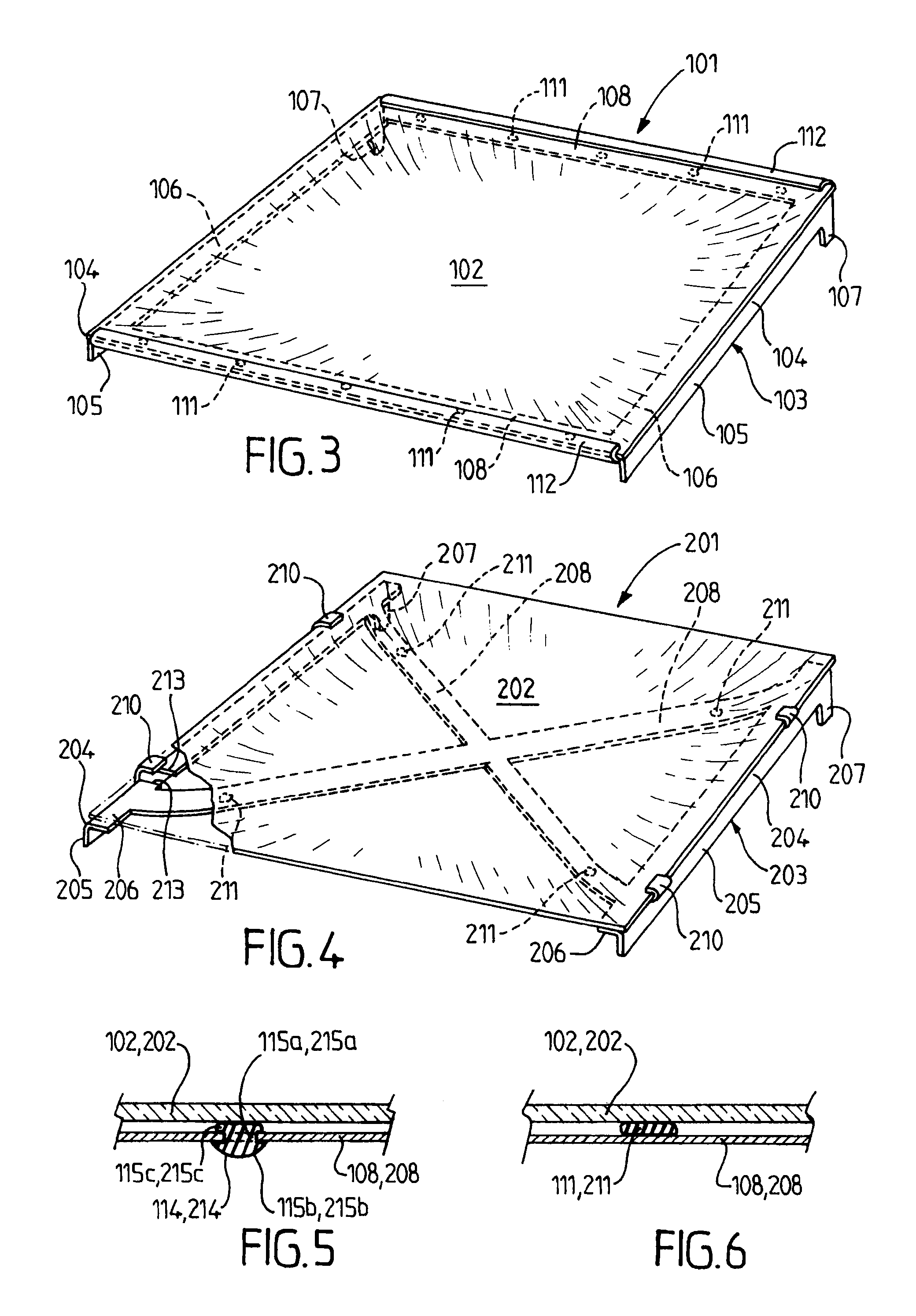
[0043]The shelf 101 of the second embodiment does not include the central crosspiece 8 as the shelf 1 does, but rather two crosspieces 108 arranged under each of the front and back edges, respectively, of the glass plate 2. The cradle 103 includes a frame of which the L-shaped side arms form the brackets 104 with their hooks 107 and the transverse arms are formed by a single L-shaped piece of which the horizontal parts form the crosspieces 208 and of which the vertical arms are folded upward to form folds 112 that project over the glass plate 102. Spots of adhesive 111 are placed in the same manner as previously on the two crosspieces 108.

[0044]The second embodiment is assembled in the same manner as the first embodiment, with the glass plate fitting laterally onto the cradle 103, the folds 112 acting as a guide during this fitting, then as a safety device, preventing the glass plate 102 from sliding when the shelf 101 is removed from its cabinet for cleaning, for example, and when ...

third embodiment

[0045]The shelf 201 of the third embodiment does not include the central crosspiece 8 of the shelf 1, but rather two crosspieces 208 which intersect at the center of the cradle 203. Tabs 210 similar to the tabs 10 of the shelf 1 are formed by cuts 213 in the part 206 of each bracket 204 starting from the inner edge, making it possible to cut out a band of material that is lifted and curved inward. Spots of adhesive 211 are placed near each end of the crosspieces 208.

[0046]The shelf 201 of the third embodiment is assembled in the same manner as the shelf 1.

[0047]Spots of adhesive 111, 211 are shown in FIG. 6, but as can be seen in FIG. 5, a hole 114, 214 can instead be provided in a crosspiece 108, 208 for the passage of a plastic stop including a central body 115a, 215a having a semi-spherical head 115b, 215b on one side and a block 115c, 215c on the other side. Such a stop is placed in each hole by insertion from below, such that its block protrudes from the inner surface of the cr...

fourth embodiment

[0048]The shelf 301 of the fourth embodiment includes, instead of the bracket 4 of the shelf 1, a hollow lateral bar 304 including a section formed of a band of material (metal, for example) folded to form an inner vertical wall 316, a lower horizontal wall 317, an outer vertical wall 305, and a sloped upper wall 306 following the curve of the glass plate 302. The lateral bar 304 is designed to be fastened with the rear hook formed on the wall 305 in order to act as a bracket against the back of the refrigerator cabinet. The two sloped upper walls are joined by a central crosspiece 308 equivalent to the crosspiece 8 of the shelf 1 and having spots of adhesive 311 to join it to the glass plate 302.


PUM


Abstract

A shelf for a cabinet, for a refrigerator or the like, includes a glass plate for holding items which is supported along its side edges by track or rail type brackets suitable for fastening or mounting in said cabinet and aligned with a support structure formed or held by said cabinet. The brackets are joined by at least one crosspiece and with said crosspiece(s) form a cradle to hold said plate that is suitable for supporting the mechanical strength of the shelf.

Description

REFERENCE TO PRIOR APPLICATIONS[0001]This application claims priority to French patent application 08 55260, filed Jul. 30, 2008, the contents of which are incorporated herein by reference.BACKGROUND OF THE INVENTION[0002]I. Field of the Invention[0003]This invention relates to a shelf or rack for holding items, configured to be fastened or mounted advantageously in a removable manner in the frame of a cabinet. In particular, it relates to a shelf suitable for use in refrigerated compartments, such as reach-in coolers, refrigeration units, and refrigerators, for holding items, especially food items, and it more particularly relates to a shelf with a curved shape, especially at its edges, for example a drip pan shape.[0004]II. Description of Related Art[0005]A similar shelf of the prior art includes an essentially transparent panel with a curved shape, usually made of glass, which is supported along its side edges by brackets or tracks or rails suitable for being fastened or mounted ...

Claims


Application Information

Patent Timeline
Patent Type & Authority Applications(United States)
IPC IPC(8): F25D23/00A47F5/00A47B96/06A47B97/00
CPCA47B96/021F25D2325/022F25D25/02
Inventor LECONTE, JEAN-GERARDVARDON, FRANCOIS
Owner SAINT-GOBAIN GLASS FRANCE
Why Eureka
Try Eureka