

Emergency Lighting Device For Operating A Light Source, In Particular An LED
- Summary
- Abstract
- Description
- Claims
- Application Information
AI Technical Summary
Benefits of technology
Problems solved by technology
Method used
Image

Examples
Embodiment Construction
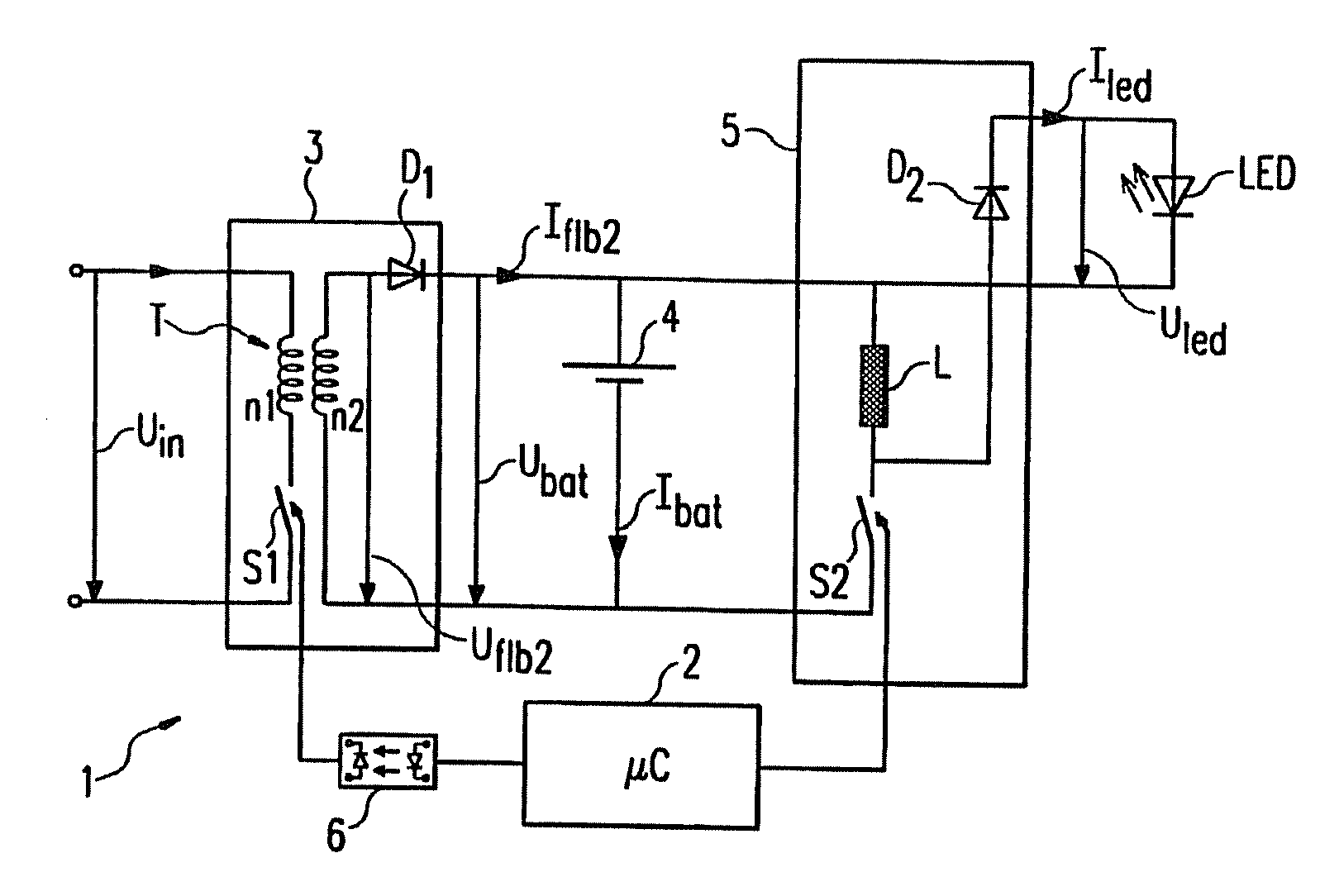
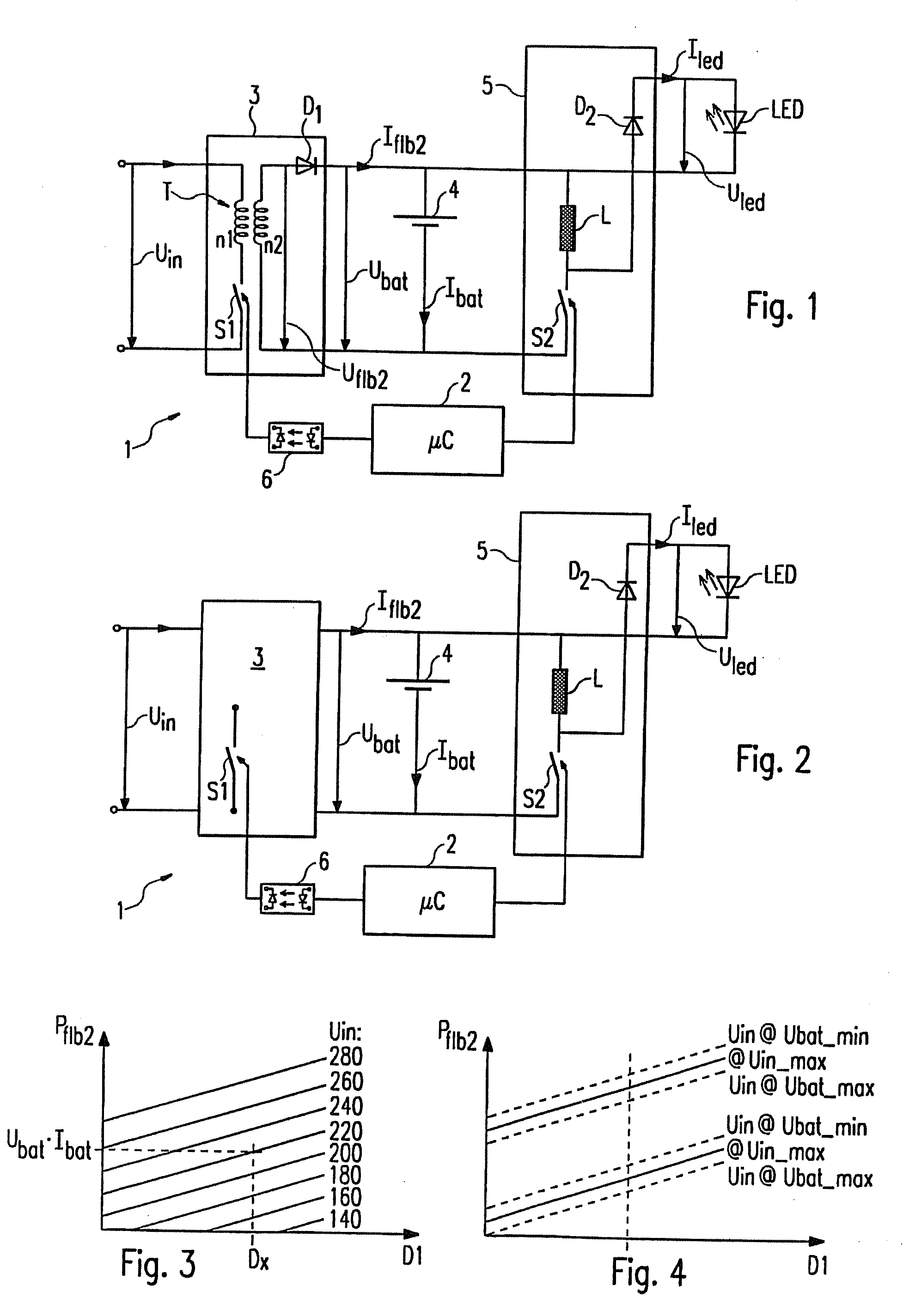
[0022]In the embodiment represented, the emergency lighting device according to the invention, which in FIG. 1 is represented in a simplified manner and denoted by the reference 1, is intended for operation of an LED as an emergency lighting source. The emergency lighting device 1 is connected, on the input side, to an electric power supply network providing a mains supply voltage Uin, and comprises, as essential components, a control unit 2, a charging circuit 3, an energy storage unit 4 in the form of a battery or accumulator, and a driver circuit 5. In the represented first embodiment, the charging circuit 3 is constituted by a so-called flyback converter that, on the one hand, has a transformer T comprising a primary winding n1 and a secondary winding n2 and, on the other hand, has a controllable switch S1. In known manner, the energy provided by the mains supply voltage Uin can be transferred to the secondary side of the flyback converter 3 through appropriate alternating openi...
PUM
 Abstract
Description
Claims
Application Information