Imaging apparatus and method

a technology of imaging apparatus and spherical tube, which is applied in the field of imaging apparatus, can solve the problems and achieve the effect of reducing the possibility of user missing a photo opportunity

Inactive Publication Date: 2010-03-04
FUJIFILM CORP
View PDF5 Cites 12 Cited by
  • Summary
  • Abstract
  • Description
  • Claims
  • Application Information

AI Technical Summary

Benefits of technology

[0038]According to the invention, it is possible to provide an imaging apparatus and method in which the possibility that the user misses a photo opportunity can be reduced as far as possible.

Problems solved by technology

In the operation, however, a time period for setting the in-focus state by the AF function must elapse from the timing when the user who intends to perform the still-picture imaging depresses the release button, to that when the still-picture imaging is actually enabled, and there is a possibility that the user misses a photo opportunity.
In all the methods, however, a time period required for setting the in-focus state by the AF function must elapse from the timing when the user intends to perform the imaging, and that when the first imaging is actually enabled, and hence the possibility that the user misses a photo opportunity remains.

Method used


Image

  • Imaging apparatus and method
  • Imaging apparatus and method
  • Imaging apparatus and method

Examples


first embodiment

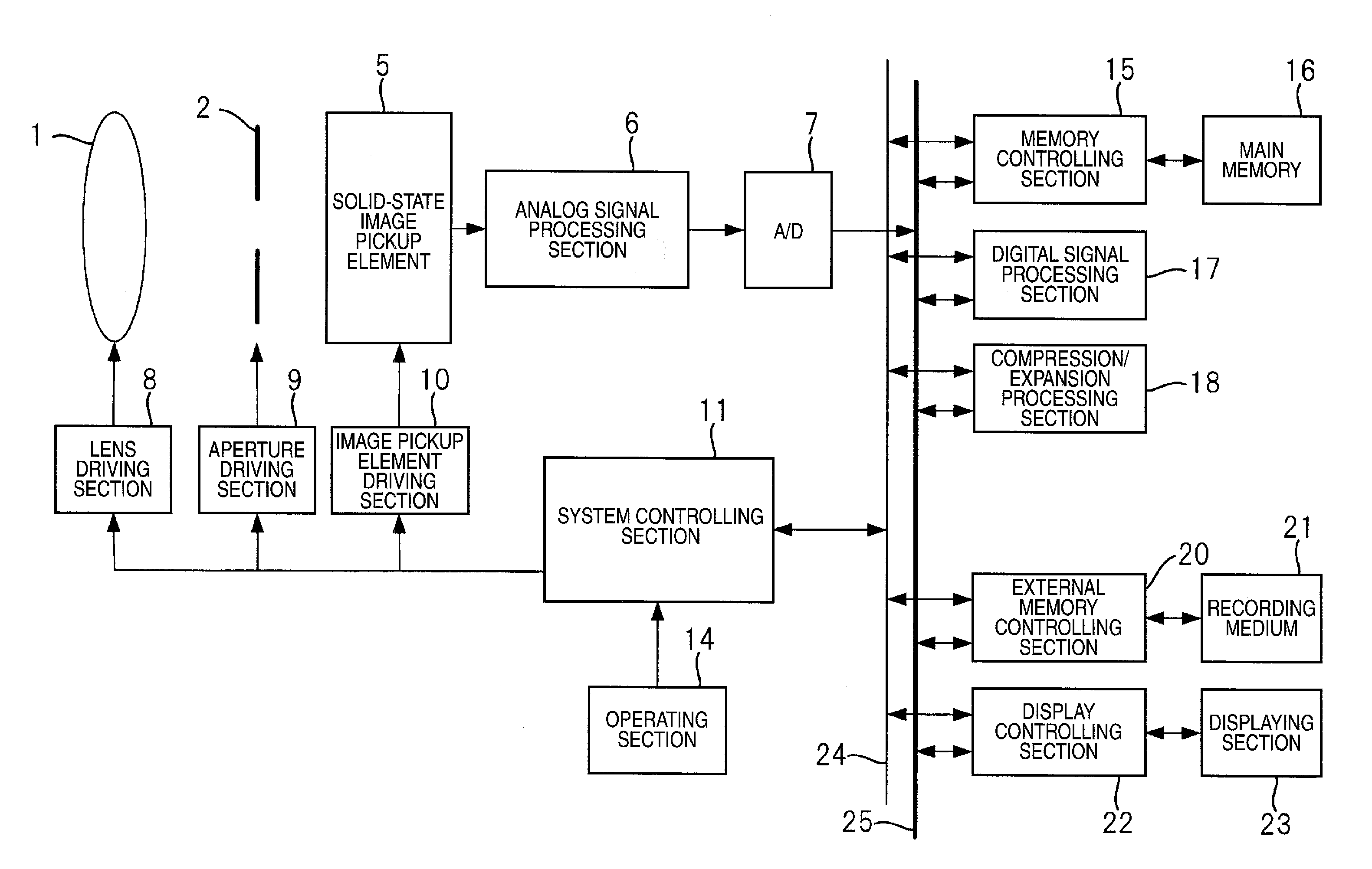
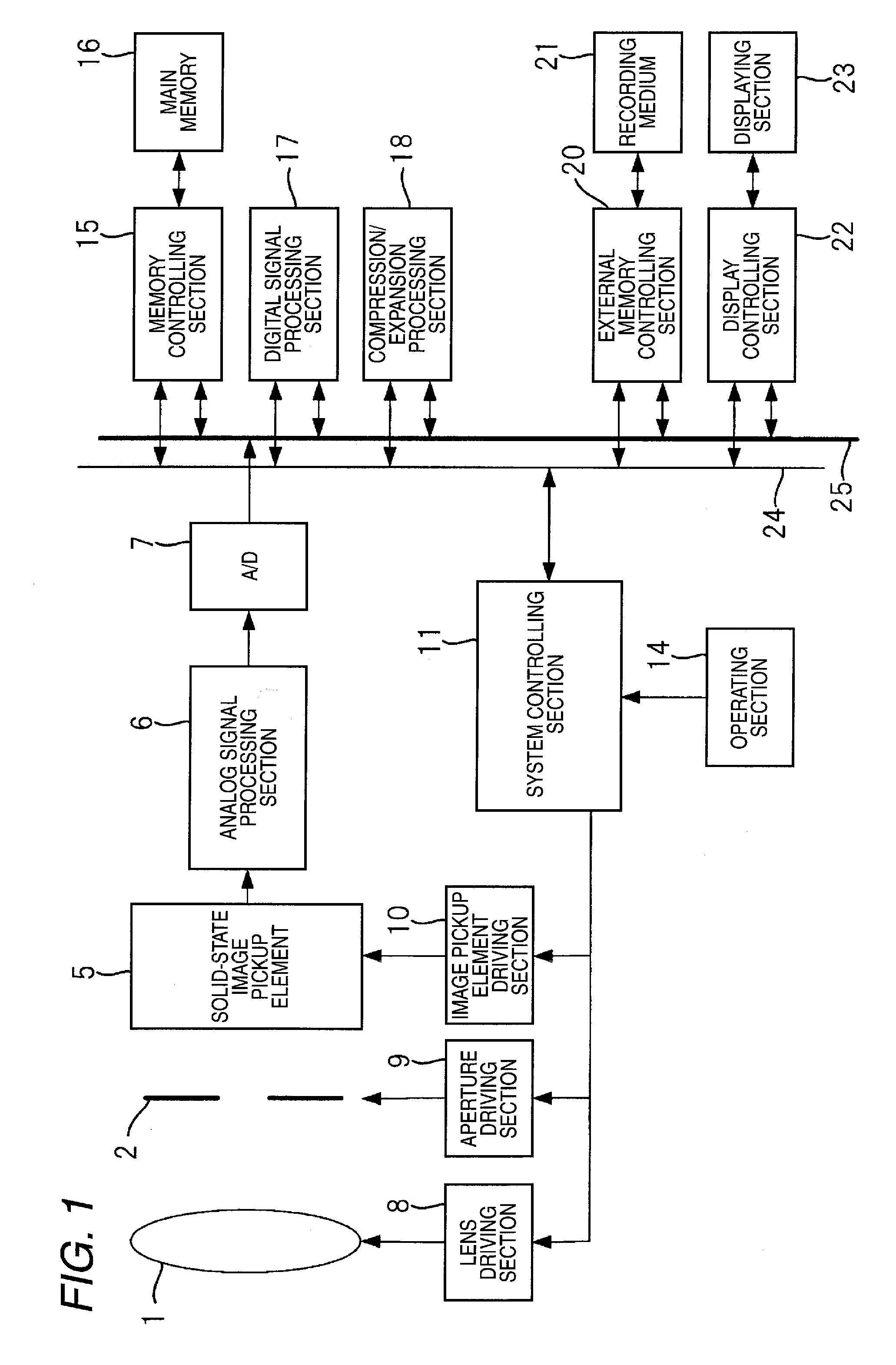
[0054]FIG. 1 is a diagram showing the configuration of a digital camera which is an example of the imaging apparatus illustrating a first embodiment of the invention.

[0055]The imaging system of the illustrated digital camera includes: an imaging lens section 1 configured by a movable focus lens, a zoom lens, and the like; a solid-state image pickup element 5 such as a CCD image sensor or a CMOS image sensor; and an aperture 2 disposed between the two components.

[0056]A system controlling section 11 which controls the whole of an electric control system of the digital camera controls a lens driving section 8 so as to adjust the focus lens included in the imaging lens section 1 to be moved to the focusing position, and perform a zoom adjustment by changing the position of the zoom lens, and also controls the opening amount of the aperture 2 through an aperture driving section 9 to adjust the exposure.

[0057]The system controlling section 11 drives the solid-state image pickup element 5...

second embodiment

[0076]FIG. 3 is a diagram schematically showing the configuration of a digital camera of a second embodiment. In FIG. 3, similar components as those of FIG. 1 are denoted by the same reference numerals.

[0077]In the digital camera shown in FIG. 3, the imaging lens section 1 of the digital camera shown in FIG. 1 can be moved not only in the direction vertical to the light receiving face of the solid-state image pickup element 5, but also in the horizontal direction, and the lens driving section 8 controls also the horizontal movement of the imaging lens section 1. The function of the system controlling section 11 is partly different from the first embodiment. A motion detecting section 3 configured by, for example, a physical sensor which detects motion (the angular velocity, the acceleration, the inclination, and the like) of the digital camera is added to the digital camera.

[0078]FIG. 4 is a view showing an operation flow in the still-picture imaging mode of the digital camera of th...

third embodiment

[0084]FIG. 5 is a diagram schematically showing the configuration of a digital camera of a third embodiment. In FIG. 5, similar components as those of FIG. 1 are denoted by the same reference numerals.

[0085]In the digital camera shown in FIG. 5, an in-focus range detecting section 19 is added to the digital camera shown in FIG. 1, and the function of the system controlling section 11 is partly changed.

[0086]Each time when the in-focus state is updated during the motion-picture imaging for displaying a through image, the in-focus range detecting section 19 calculates an in-focus range (a range where in-focus is regarded to be attained) in the in-focus state. When the in-focus state is set to the pan focus state, for example, the in-focus range can be calculated from the position of the focus lens.

[0087]FIG. 6 is a view showing an operation flow in the still-picture imaging mode of the digital camera of the third embodiment. In FIG. 6, the same processes as those of FIG. 2 are denoted...


PUM


Abstract

An imaging apparatus includes a movable focus lens, and the apparatus includes an imaging unit which, when a first instruction for starting setting of an in-focus state for still-picture imaging is given during motion-picture imaging for displaying a through image, performs first still-picture imaging while maintaining an in-focus state in the motion-picture imaging for displaying a through image.

Description

CROSS-REFERENCE TO RELATED APPLICATIONS[0001]This application claims the benefit of Japanese Patent Application JP 2008-218588, filed Aug. 27, 2008, the entire content of which is hereby incorporated by reference, the same as if set forth at length.FIELD OF THE INVENTION[0002]The present invention relates to an imaging apparatus including a movable focus lens, and an imaging method which is performed by the imaging apparatus.BACKGROUND OF THE INVENTION[0003]Usually, an imaging apparatus such as a digital camera or a digital video camera is provided with a lens system for imaging an object image on an imaging element. The lens system includes: a zoom lens configured by a plurality of lens groups; and a focus lens for focusing an object image to be taken.[0004]When an image of an object is to be taken, the focal length of the lens system is changed by driving the zoom lens so that the range of the imaging angle (field angle) can be set to a desired value, and a focusing control is aut...

Claims


Application Information

Patent Timeline
Patent Type & Authority Applications(United States)
IPC IPC(8): H04N5/232
CPCH04N5/23245H04N5/23212H04N23/675H04N23/667
Inventor IRIE, FUMINORI
Owner FUJIFILM CORP
Why Eureka
Try Eureka