Image capturing apparatus and image capturing method

a technology image, which is applied in the field of image capturing apparatus, can solve the problems of difficult to satisfactorily track the state of high-level changes of objects, and the inability to provide images at the desired timing,

Inactive Publication Date: 2007-02-01
CANON KK
View PDF14 Cites 151 Cited by
  • Summary
  • Abstract
  • Description
  • Claims
  • Application Information

AI Technical Summary

Benefits of technology

[0022] The present invention has been made to overcome the conventional drawbacks, and has as its object to provide a technique associated with an image capturing apparatus which does not require any large-capacity memory and can acquire an image in a more proper state. It is another object of the present invention to provide a technique capable of simultaneously photographing moving images which are successively photographed, and high-quality still images, and photographing high-quality still images without influencing moving image photographing and missing any photo opportunity.

Problems solved by technology

However, the timing when an image in an optimal state is input cannot be set or predicted.
Thus, in order to select an image, unnecessary image data must be recorded, requiring a large-capacity memory.
It is difficult to satisfactorily track an object state which changes at high speed, and obtain a high-quality image at a normal recording rate.
Further, interpolation does not always provide an image at a desired timing.
It is difficult to track a moving object when the illumination condition changes or the image capturing apparatus itself moves.
However, it is generally hard to properly set a partial area to be extracted from an input image.
When a tracked object is out of focus upon variations in photographing conditions or the illumination condition varies, the performance to track an object which moves and changes at high speed cannot be maintained.
If a pattern of a motion vector similar to an object during tracking exists on the background, the background object may be erroneously recognized and tracked.
However, a time lag is generated in switching from the moving image photographing mode to the still image photographing mode, and the user may miss a photo opportunity in pressing the shutter button.
As a result, photographing likely fails because an advanced technique of, e.g., predicting a change and releasing the shutter is required to prevent an image in which the eyes of an object are shut due to an instantaneous blink, or to capture the moment of a good facial expression such as a smile.
However, the apparatus becomes bulky, and it is difficult to control the two optics in synchronism with each other.
Moreover, the two optics do not always coincide with each other in view angle, focus status, and F-number, and an intended image is less likely obtained.

Method used


Image

  • Image capturing apparatus and image capturing method
  • Image capturing apparatus and image capturing method
  • Image capturing apparatus and image capturing method

Examples


first embodiment

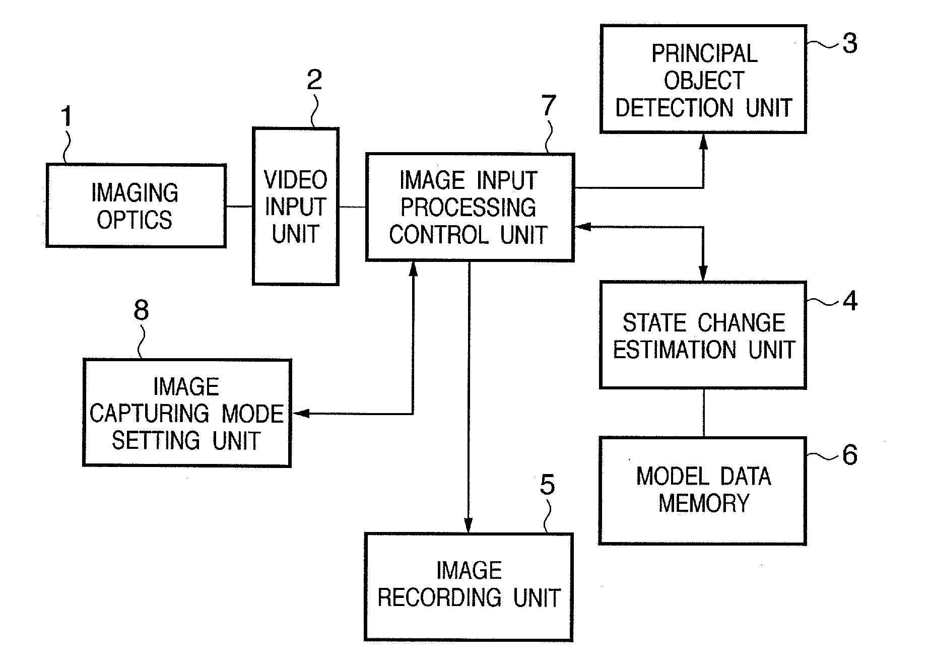
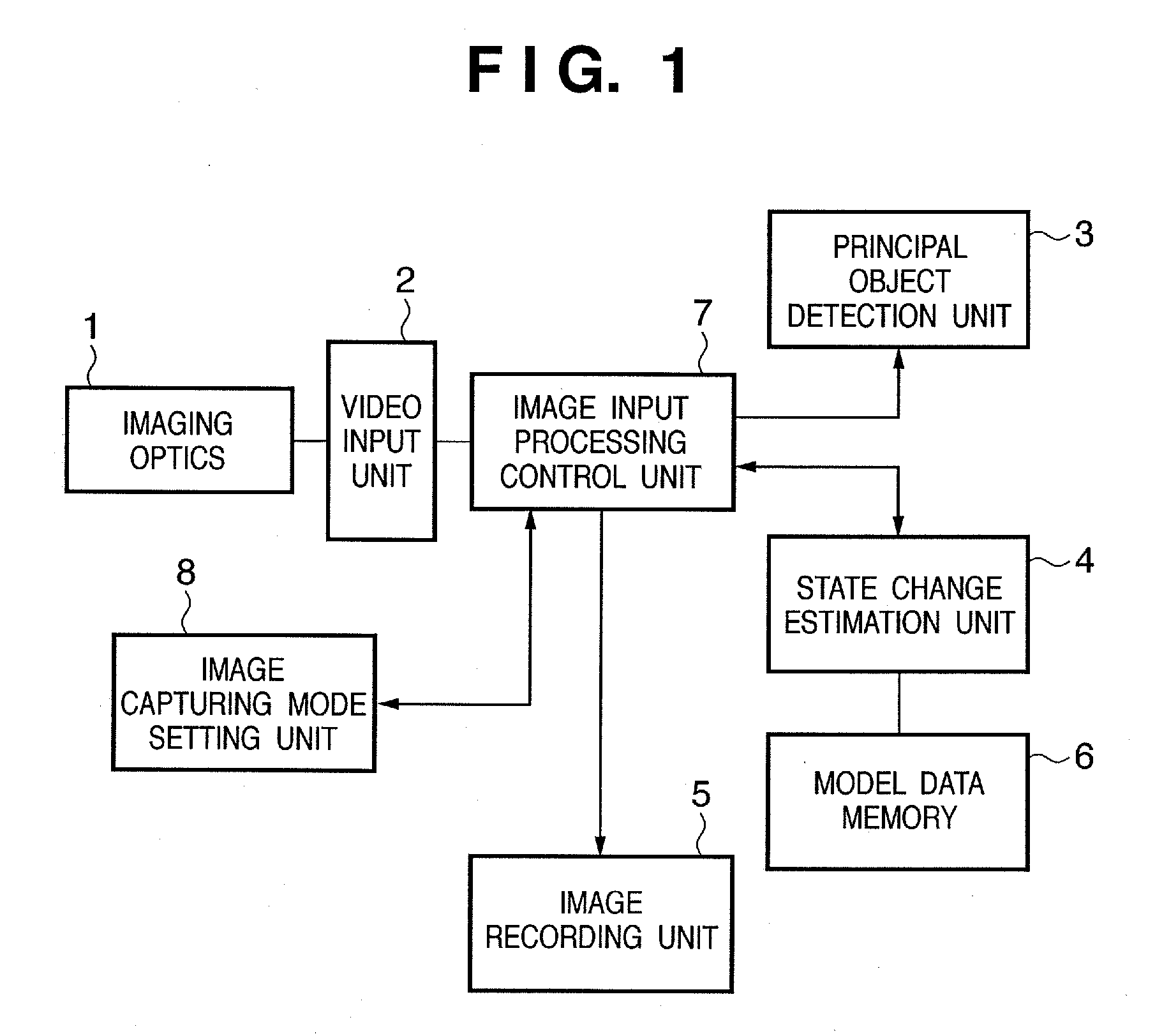
[0056] As shown in FIG. 1, the image capturing apparatus comprises an imaging optics 1, video input unit 2, principal object detection unit 3, state change estimation unit 4, model data memory 6, image input processing control unit 7, image capturing mode setting unit 8, image recording unit 5, and the like. An outline of the function of each building unit is as follows.

[0057] The imaging optics 1 comprises of a lens and the like, and forms an image on the basis of light traveling from an object.

[0058] The video input unit 2 photoelectrically converts an image formed by the imaging optics 1, and outputs the image as image data. The video input unit 2 is made up of a video (optical) sensor such as a CCD (Charge-Coupled Device), a sensor signal processing circuit, a sensor driving circuit, and the like. The video input unit 2 is typically formed using a CMOS image sensor and the like. The video input unit 2 outputs a predetermined video signal (image data) in response to a read cont...

second embodiment

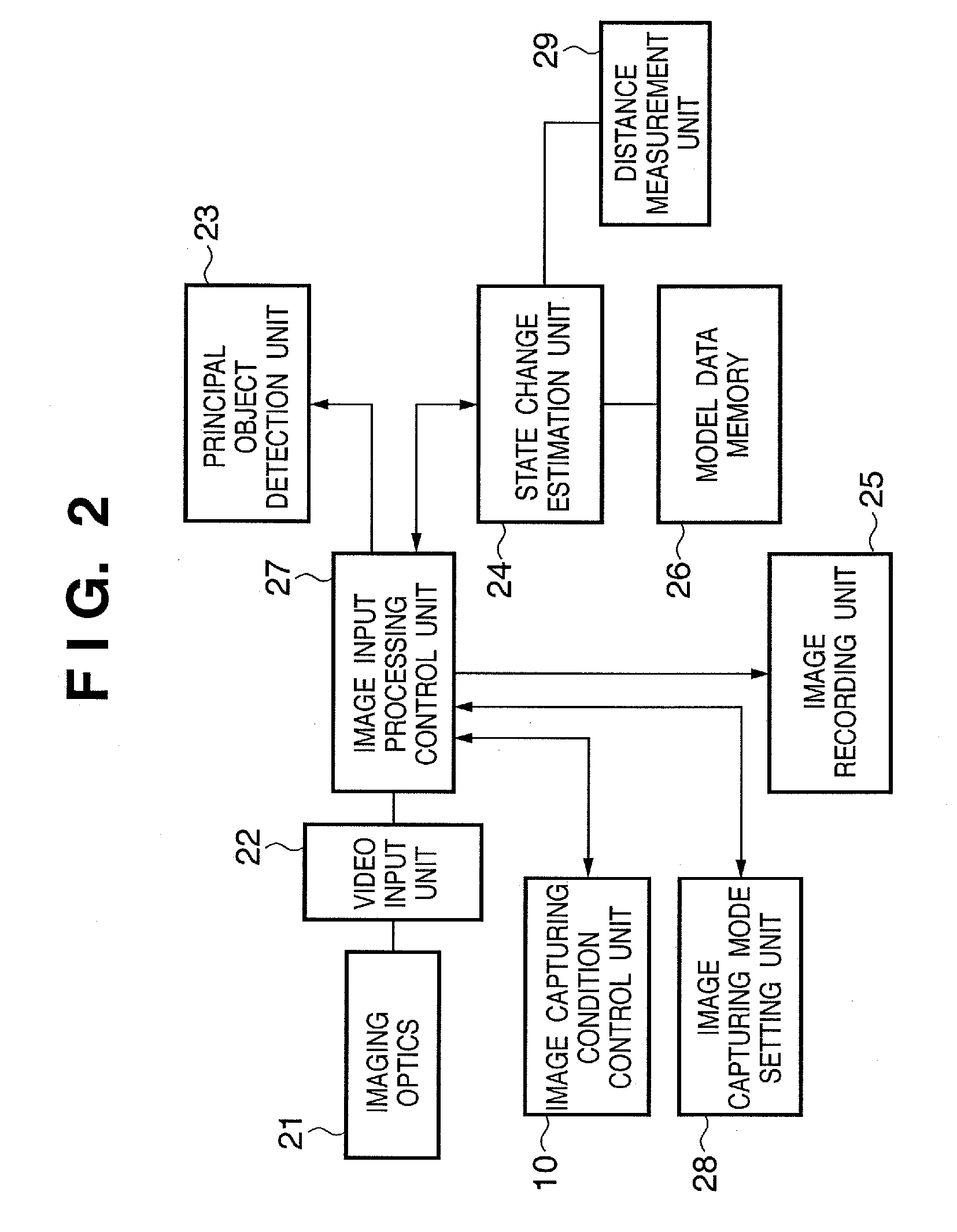
[0130] The image capturing condition control unit 10 controls photographing conditions such as the exposure and focus on the basis of a prediction signal input from the state change estimation unit 24. For example, when an object moves quickly apart from the image capturing apparatus, a general AF (Automatic Focus) device cannot track or control an accurate in-focus state. To solve this problem, the (autonomous) image capturing apparatus incorporates a predetermined distance measurement unit 29 which measures the distance between an object and the image capturing apparatus. The state change estimation unit 24 generates a prediction signal associated with the object distance on the basis of a signal which is output from the distance measurement unit 29 and associated with the distance to the object. In accordance with the prediction signal, the image capturing condition control unit 10 performs positioning control of a focus control lens motor. In this case, the state change estimat...

third embodiment

[0150] In the third embodiment, in addition to the above configuration, image capturing conditions are automatically controlled (changed) on the basis of the result of detecting the motion pattern of a principal object (person) (the contents of the motion pattern).

[0151]FIG. 6 is a block diagram showing the configuration of the main part of an image capturing apparatus according to the third embodiment. As shown in FIG. 6, the image capturing apparatus according to the third embodiment comprises an imaging optics 31, video input unit 32, principal object detection unit 33, state change estimation unit 34, image recording unit 35, model data memory 36, image input processing control unit 37, image capturing mode setting unit 38, and image capturing condition control unit 300. These units are the same as the units 1 to 8 in FIG. 1 and the unit 10 in FIG. 2, and a detailed description thereof will be omitted.

[0152] In addition to the above configuration, the image capturing apparatus ...


PUM


Abstract

In an image capturing apparatus, a video input unit (2) captures the image of an object and sequentially acquires image data associated with the image capturing, a model data memory (6) stores model data associated with the first feature quantity calculated from a feature point of the object in a model image, a principal object detection unit (3) calculates the second feature quantity from a feature point of the object in the acquired image data, a state change estimation unit (4) estimates, on the basis of the second feature quantity and the model data, the timing when the object satisfies a predetermined condition, and an image input processing control unit (7) stores the image data corresponding to the estimated timing in an image recording unit (5). This configuration makes the image capturing apparatus acquire an image in a more proper state without large-capacity memory.

Description

BACKGROUND OF THE INVENTION [0001] 1. Field of the Invention [0002] The present invention relates to an image capturing apparatus and, more particularly, to an image capturing apparatus which automatically captures an image in accordance with image capturing conditions. The present invention also relates to an image capturing technique of simultaneously photographing moving and still images. [0003] 2. Description of the Related Art [0004] There has conventionally been known a technique associated with an image capturing apparatus which automatically captures an image in accordance with image capturing conditions. [0005] Japanese Patent Laid-Open No. 2000-259833 discloses a technique of determining the state of a person's face from successive images and selecting an image exhibiting an optimal face state. [0006] Japanese Patent No. 3240339discloses a technique of, when an image at a timing desired by the user does not exist, performing interpolation processing using pixel corresponde...

Claims


Application Information

Patent Timeline
Patent Type & Authority Applications(United States)
IPC IPC(8): G03B17/00
CPCG03B17/16G06K9/00248G06T7/0022H04N5/232G06K9/00315H04N5/23222H04N5/772H04N2101/00H04N5/23219G06T7/97G06V40/165G06V40/176H04N23/67H04N23/61H04N23/64H04N23/611G06T1/00G06T1/60G06T7/40
Inventor MATSUGU, MASAKAZUMORI, KATSUHIKOKANEDA, YUJIHAYASHI, TADASHI
Owner CANON KK
Why Eureka
Try Eureka