Shield

a shielding and shielding technology, applied in the direction of electrical apparatus construction details, support structure mounting, rack/frame construction, etc., can solve the problems of shield damage, inconvenient shielding, and inability to use,

Inactive Publication Date: 2010-03-04
SHENZHEN FUTAIHONG PRECISION IND CO LTD +1
View PDF10 Cites 50 Cited by
  • Summary
  • Abstract
  • Description
  • Claims
  • Application Information

AI Technical Summary

Problems solved by technology

However, such a shield is inconvenient when repairing the electronic components protected thereby, s

Method used


Image

  • Shield
  • Shield
  • Shield

Examples


Embodiment Construction

[0013]The disclosed shield is suitable for electronic devices, such as mobile phones, PDAs (personal digital assistants), and the like. Other applications with a similar use for the shield employed are equally applicable.

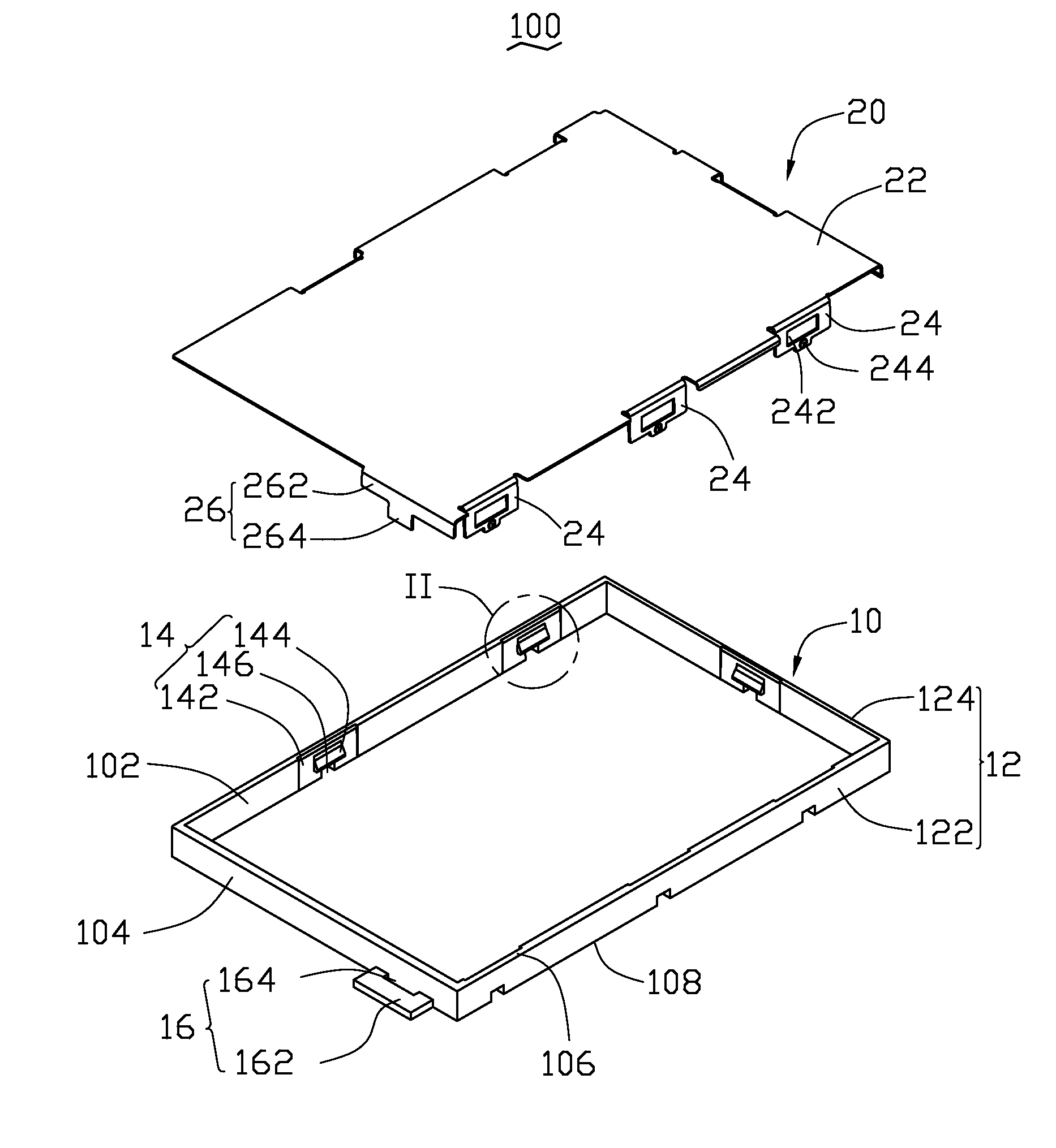
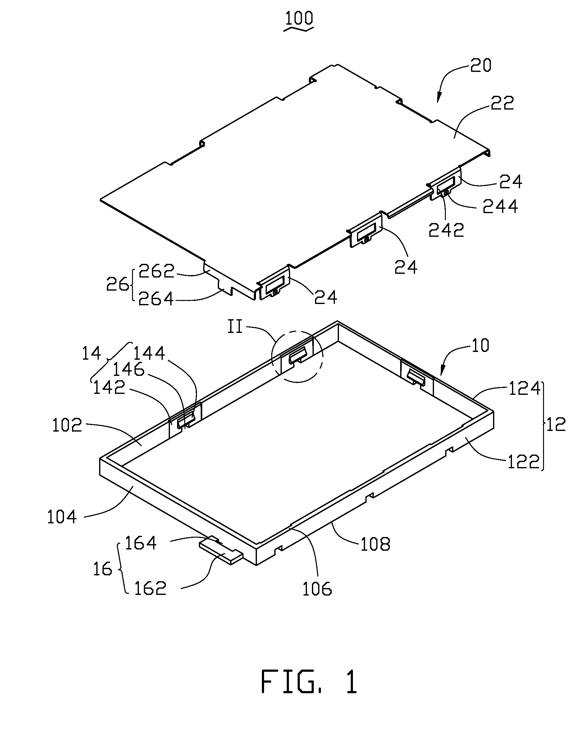
[0014]Referring to FIGS. 1 and 2, a shield 100 according to an exemplary embodiment includes a frame 10 and a cover 20 covering the frame 10.

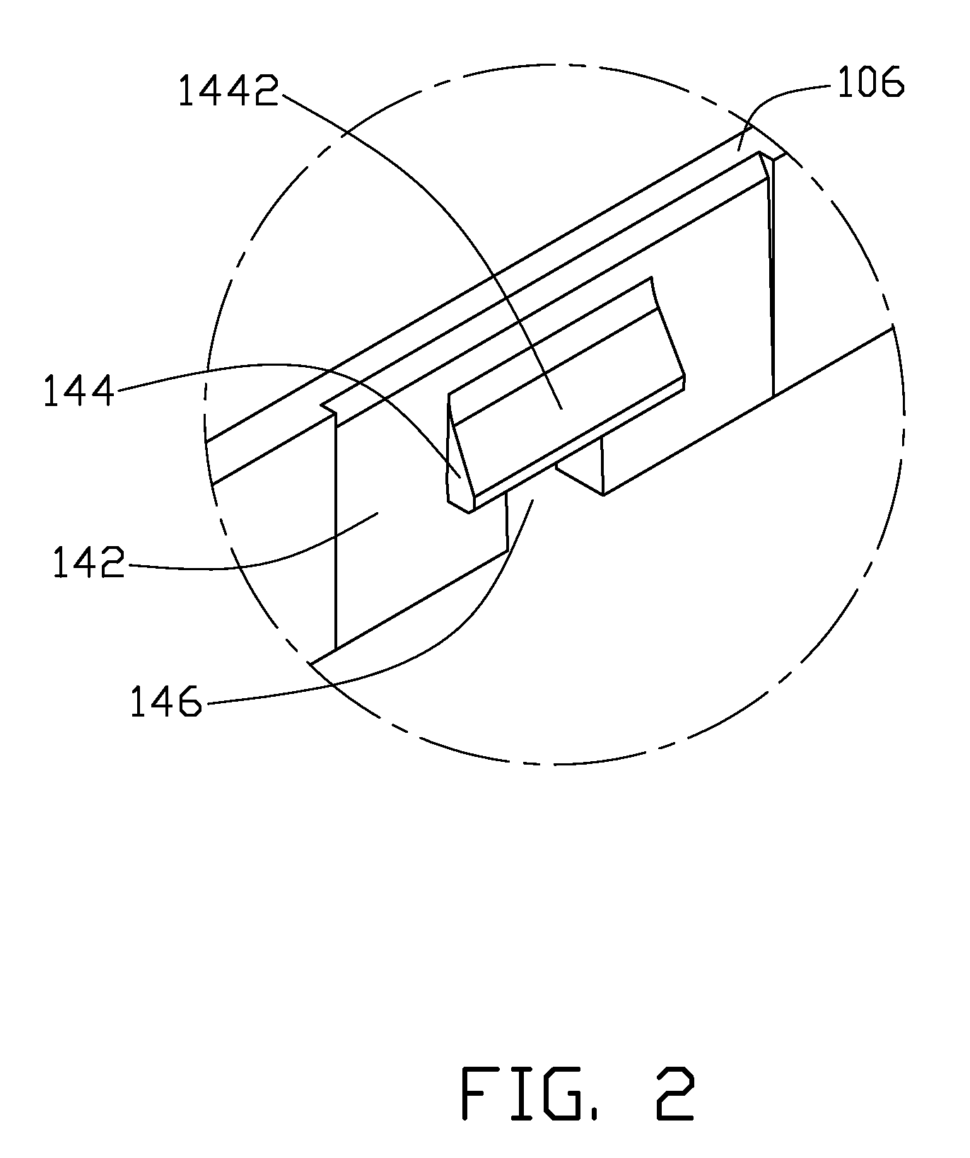
[0015]The frame 10 includes a peripheral wall 12, a plurality of fixed portions 14 separately formed on the peripheral wall 12 and a locking portion 16 formed on the peripheral wall 12. The peripheral wall 12 includes two opposite and parallel side walls 122 and two opposite and parallel end walls 124. Each side wall 122 is perpendicularly connected to each end wall 124 to form the frame 10. The frame 10 has an inner side surface 102, an outer side surface 104, a top surface 106 and a bottom surface 108. One side wall 122 has two fixed portions 14 formed on the inner side surface 102, the other side wall 122 has three fixed por...


PUM


Abstract

A shield for electronic elements of a circuit board includes a frame and a cover, the frame including a peripheral wall comprising a plurality of fixed portions thereon, wherein the fixed portion includes a protrusion and a gap, the protrusion formed on the inner side of the peripheral wall, and the cover has a plurality of folding pieces corresponding to the fixed portions, the folding pieces defines an aperture, and the cover is mounted on the frame, the folding pieces match with the fixed portions correspondingly, the protrusion passes the aperture and locks with the aperture. When the cover is detached, the folding pieces are resisted via the gap to make the protrusion to break away from the aperture of the folding piece, enabling the cover to be opened.

Description

BACKGROUND [0001]1. Field of the Invention[0002]The exemplary invention relates to electromagnetic shielding, and particularly to a shield for portable electronic devices.[0003]2. Description of Related Art[0004]Many electronic components in electronic device, such as capacitors, are surrounded by a shield protecting the electronic components from external electromagnetic waves and unwanted electromagnetic waves from the system. Generally, a typical shield is made by punching a metal piece. The shield is soldered to a circuit board of the electronic device to shield the electronic components.[0005]However, such a shield is inconvenient when repairing the electronic components protected thereby, since access is, obviously, restricted. When an electronic component needs to be repaired, the shield must be dismounted completely. In the process, the shield may be damaged and become unusable.[0006]Therefore, there is room for improvement within the art.BRIEF DESCRIPTION OF THE DRAWINGS[00...

Claims


Application Information

Patent Timeline
IPC IPC(8): H05K9/00
CPCH05K9/0032H05K5/0013
Inventor SHI, ZHENGCHANG, CHIH-CHIANGZHANG, HONG-WEI
Owner SHENZHEN FUTAIHONG PRECISION IND CO LTD
Why Eureka
Try Eureka