Snuff box

a snuff box and box body technology, applied in the field of snuff boxes, can solve the problems of large number of components, disadvantageous consumption of the volume of the whole snuff box, and inability to meet the needs of mass production,

Inactive Publication Date: 2010-03-18
SNUSMUMRIK
View PDF6 Cites 56 Cited by
  • Summary
  • Abstract
  • Description
  • Claims
  • Application Information

AI Technical Summary

Problems solved by technology

Snuff boxes with a fixed such volume is today available on the market, but the storage space for used snuff disadvantageously consum...

Method used


Image

  • Snuff box
  • Snuff box
  • Snuff box

Examples


Embodiment Construction

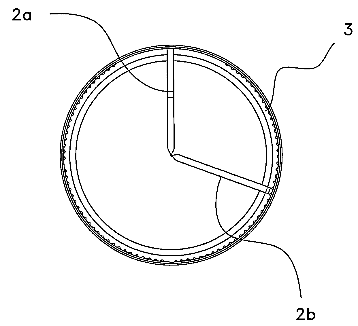
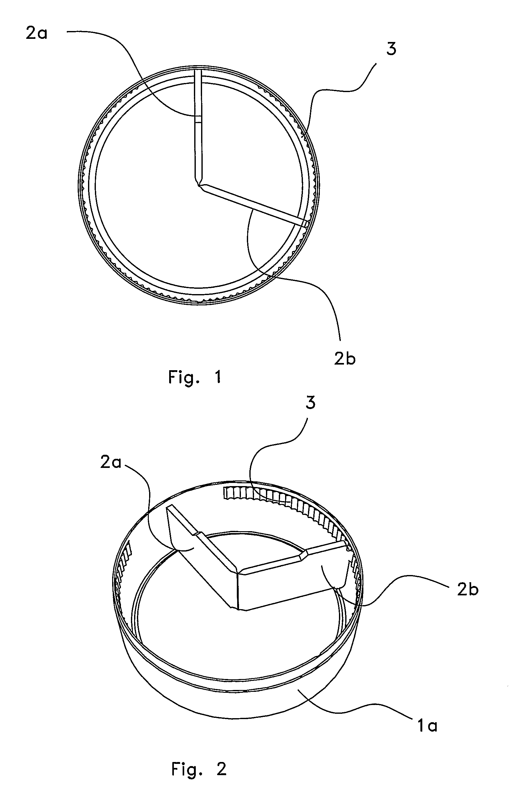
[0019]FIGS. 1 and 2 show a first embodiment of the snuff box bottom part 1a seen from above and at an oblique angle from above, respectively. The bottom part 1a is essentially cylindrical with a covered bottom and is adapted for receiving a lid. In the bottom part 1a is a dividing wall 2a, 2b with two halves arranged, a fixed dividing wall part 2a and a moveable dividing wall part 2b. The fixed dividing wall part 2a is a plane piece of material that extends from the cylinder wall towards the box centre and is fixedly arranged in this position. From the centre axis of the box a moveable dividing wall part 2b extends towards the cylinder wall. The moveable dividing wall part 2b is attached to the moveable, but in such a way that it can be pivoted relative to that.

[0020]On the cylinder wall interior a number of recesses 3 are arranged and a protruding portion of the moveable dividing wall part 2b is normally placed in one of these recesses. If the moveable dividing wall part is made to...


PUM


Abstract

The invention relates to a snuff box comprising a lid, a bottom part and a dividing wall which divides the interior of the snuff box in two volumes. The dividing wall is moveably arranged but the snuff box comprises only two separate continuous elements and may under optimal circumstances advantageously be moulded in only two process steps. The invention further relates to such a snuff box where the lid comprises a driving element arranged to shift the dividing wall. Further the invention relates to such a snuff box where the dividing wall is divided into two dividing wall parts, a first dividing wall part fixedly attached to the bottom part and a second dividing wall part fixedly attached to the lid. Yet further the invention relates to such a snuff box where the lid is provided with two lid portions which advantageously give separate access the two volumes that the dividing wall separates the box into.

Description

[0001]The present invention relates to a snuff box according to the introductory portions of the independent claims.BACKGROUND OF THE INVENTION [0002]When using snuff, and then in particular portion-packed snuff, there is a need for snuff boxes with a separate volume intended for used snuff. Snuff boxes with a fixed such volume is today available on the market, but the storage space for used snuff disadvantageously consumes part of the volume of the whole snuff box. A way of circumventing this is to divide the snuff box in two portions with a moveable separator and one of the earliest patents relating to such snuff boxes is disclosed by U.S. Pat. No. 2,092,219. The snuff box comprises a lid, a bottom and a separator constituted by two metal plates attached to each other by a hinge, where the two parts are pressed against each other with a spring. The design comprises a large number of components and is not well suited for mass production.[0003]An object of the invention is therefore...

Claims


Application Information

Patent Timeline
IPC IPC(8): A24F23/00
CPCA24F23/00B65D2209/00B65D25/06
Inventor BERGSTROM, NIKLASBEIJER, TUEGREEN-OHRN, CAROLINE
Owner SNUSMUMRIK
Why Eureka
Try Eureka