Lift chair and a chair frame with a position holding mechanism for use therewith

Active Publication Date: 2010-03-25
I TRUST BETTER LIFE CORP
View PDF3 Cites 21 Cited by
  • Summary
  • Abstract
  • Description
  • Claims
  • Application Information

AI Technical Summary

Benefits of technology

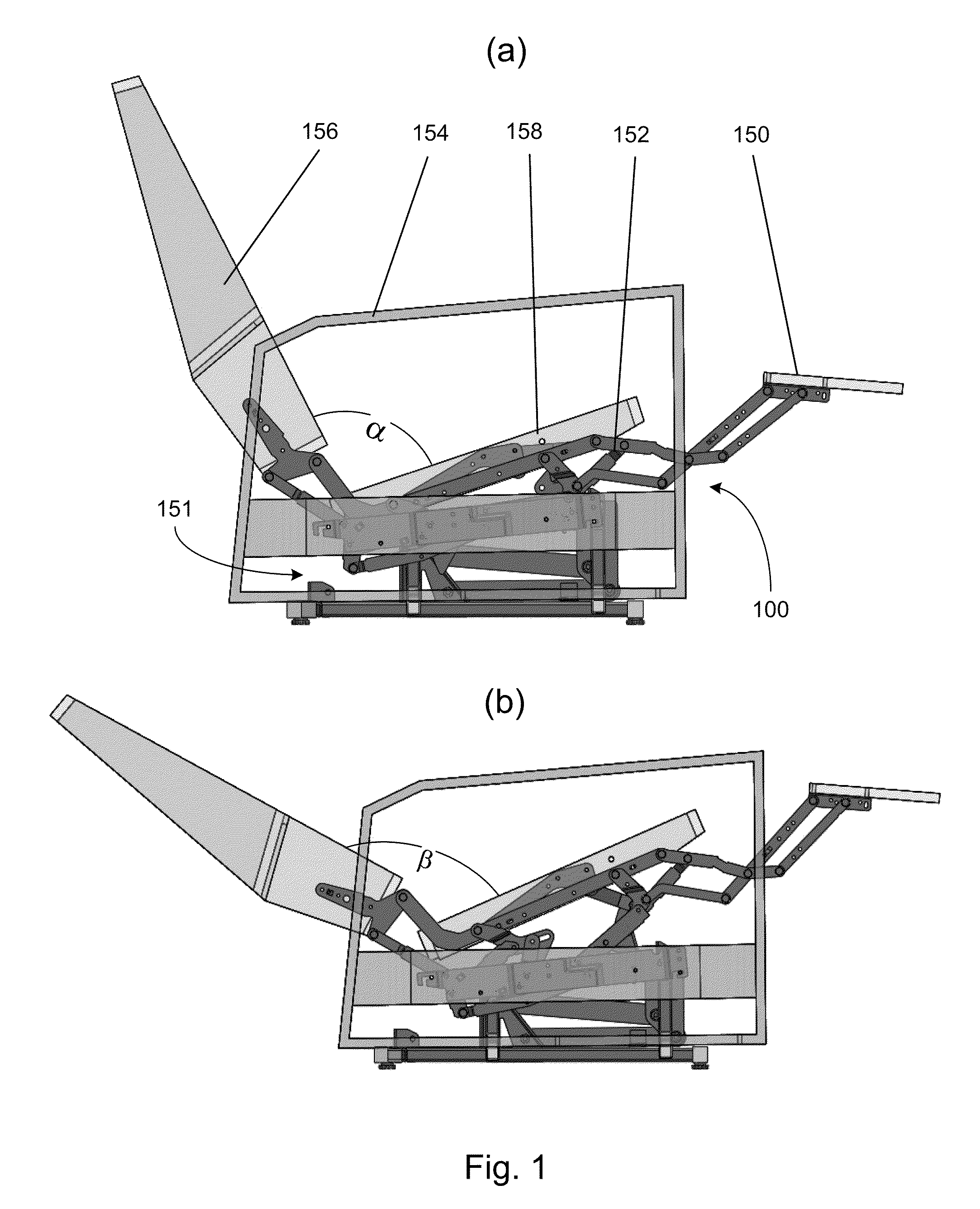
[0021]When the base mounting plate moves to a desired position between the most rearward and forward positions, the footrest linkage is in the extended position, and the seat mounting link define a thir

Problems solved by technology

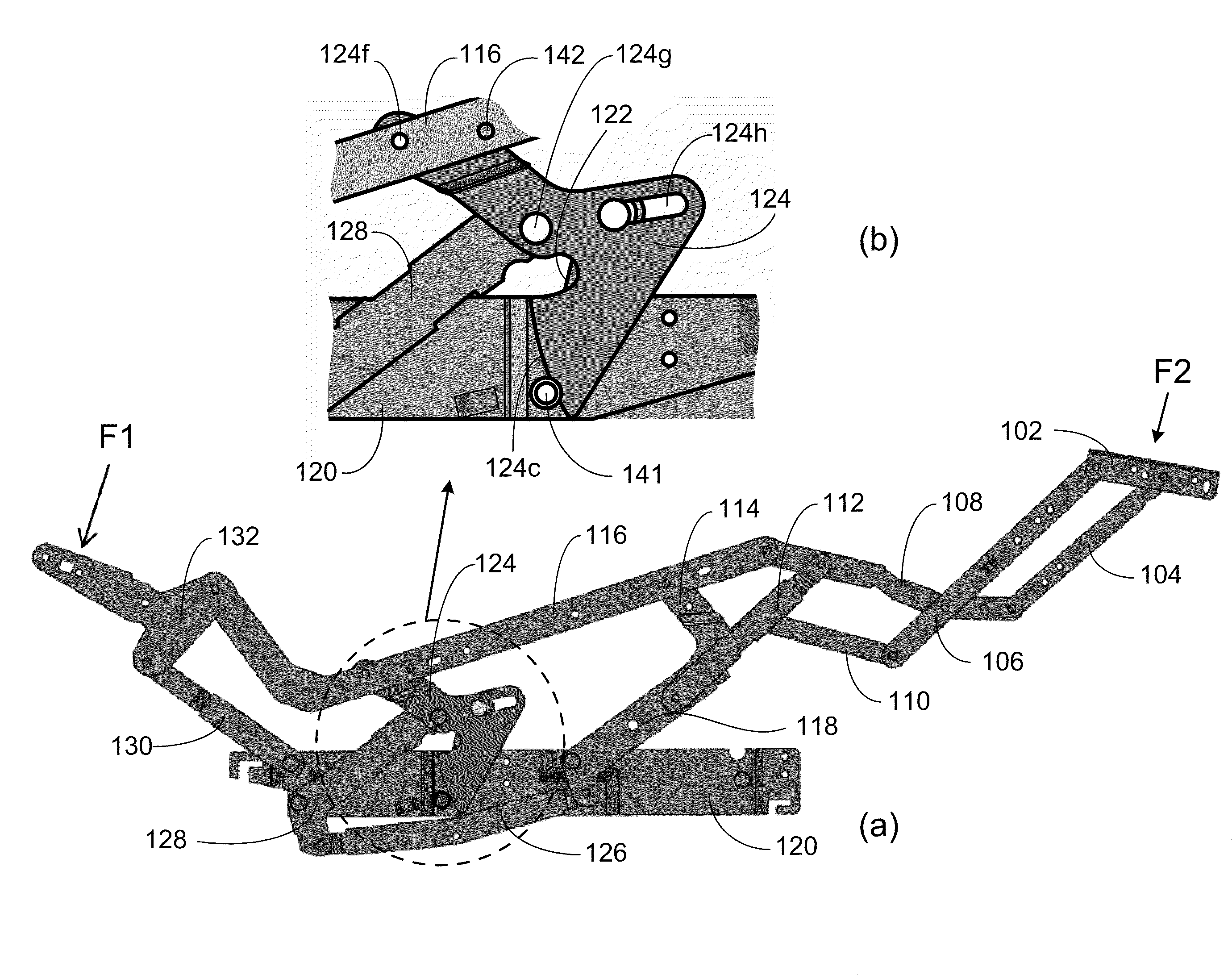
For such a design, however, it has been found that when the lift chair is in the full recline position, an unintended falling of the footrest 7 may occur when the footrest 7 is idle, i.e., no force applied thereto, or when a force, F

Method used


Image

  • Lift chair and a chair frame with a position holding mechanism for use therewith
  • Lift chair and a chair frame with a position holding mechanism for use therewith
  • Lift chair and a chair frame with a position holding mechanism for use therewith

Examples


Embodiment Construction

[0035]The present invention is more particularly described in the following examples that are intended as illustrative only since numerous modifications and variations therein will be apparent to those skilled in the art. Various embodiments of the invention are now described in detail. Referring to the drawings, like numbers indicate like components throughout the views. As used in the description herein and throughout the claims that follow, the meaning of “a”, “an”, and “the” includes plural reference unless the context clearly dictates otherwise. Also, as used in the description herein and throughout the claims that follow, the meaning of “in” includes “in” and “on” unless the context clearly dictates otherwise.

[0036]The terms used in this specification generally have their ordinary meanings in the art, within the context of the invention, and in the specific context where each term is used. Certain terms that are used to describe the invention are discussed below, or elsewhere ...


PUM


Abstract

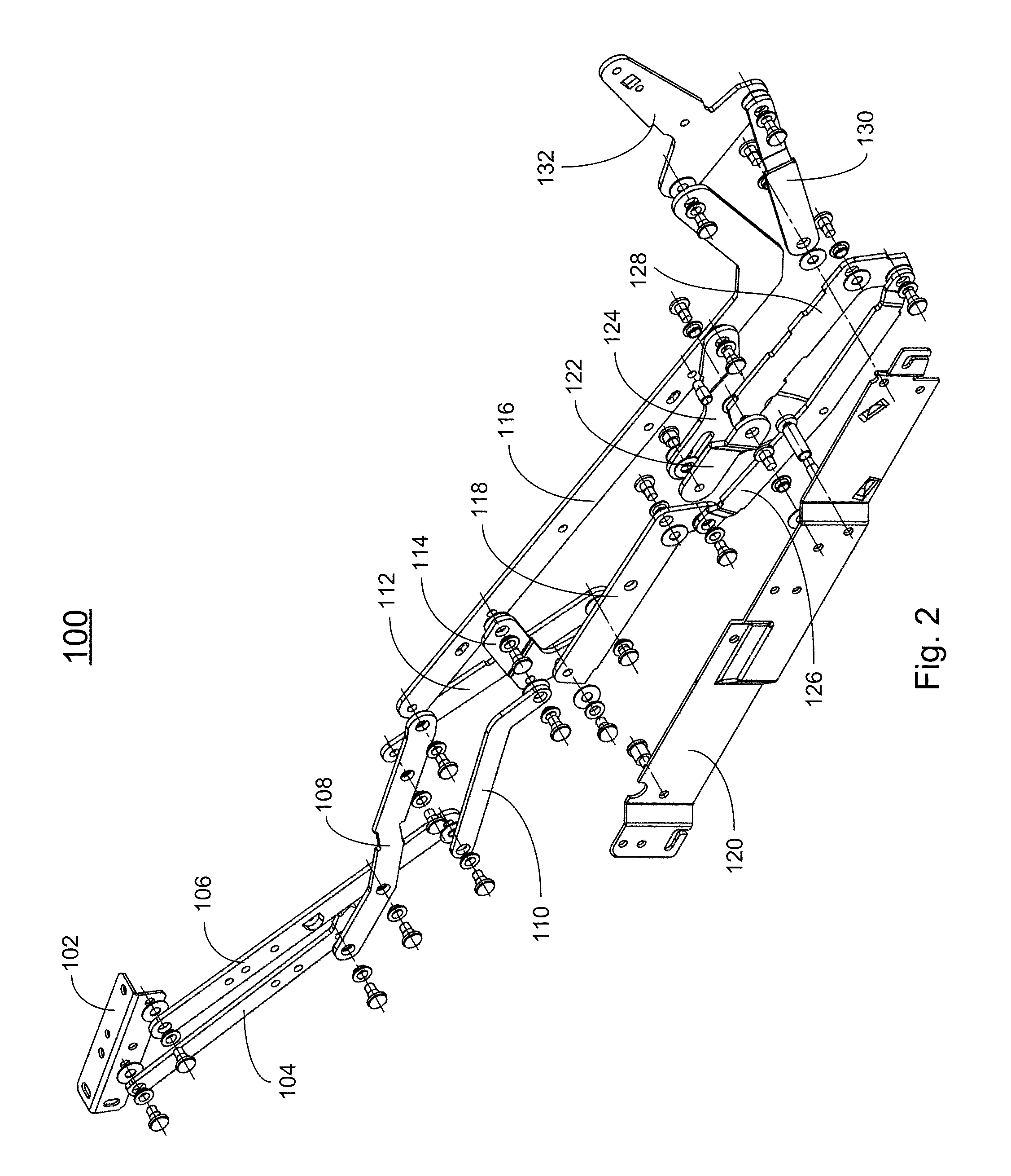
In one aspect, the present invention relates a reclining lift chair frame used in a reclining lift chair. The reclining lift chair frame utilizes a position holding mechanism to eliminate the free (idle) fall of the footrest of the reclining lift chair.

Description

CROSS-REFERENCE TO RELATED PATENT APPLICATION[0001]This application claims priority to and the benefit of, pursuant to 35 U.S.C. §119(e), U.S. provisional patent application Ser. No. 61 / 099,571, filed Sep. 24, 2008, entitled “THREE-WAY RECLINING MECHANISMS WITH STOP-PIN AND ROLLER WORKING IN CONJUNCTION WITH MECHANISMS LINKAGE TO ELIMINATE FREE FALL,” by Jian-Ming QIU, Yan-Jun ZHANG, Zhi-Liang GAO, and Xiao-Xiang ZHANG, the content of which is incorporated herein in its entirety by reference.[0002]Some references, which may include patents, patent applications and various publications, are cited in a reference list and discussed in the description of this invention. The citation and / or discussion of such references is provided merely to clarify the description of the present invention and is not an admission that any such reference is “currently available” to the invention described herein. All references cited and discussed in this specification are incorporated herein by reference...

Claims


Application Information

Patent Timeline
IPC IPC(8): A47C1/035G05G5/06A47C1/02A47C7/00A61G5/14
CPCY10T74/2066A47C1/0355
Inventor QIU, JIAN-MINGZHANG, YAN-JUNGAO, ZHI-LIANGZHANG, XIAO-XIANG
Owner I TRUST BETTER LIFE CORP
Why Eureka
Try Eureka