

Flooring panel with first and second decorative surfaces
a technology of decorative surfaces and flooring panels, applied in the field of flooring panels, can solve the problems of difficult mixing multiple visible designs in a single flooring application, and achieve the effect of improving the appearance and durability of the surfa
- Summary
- Abstract
- Description
- Claims
- Application Information
AI Technical Summary
Problems solved by technology
Method used
Image

Examples
first embodiment
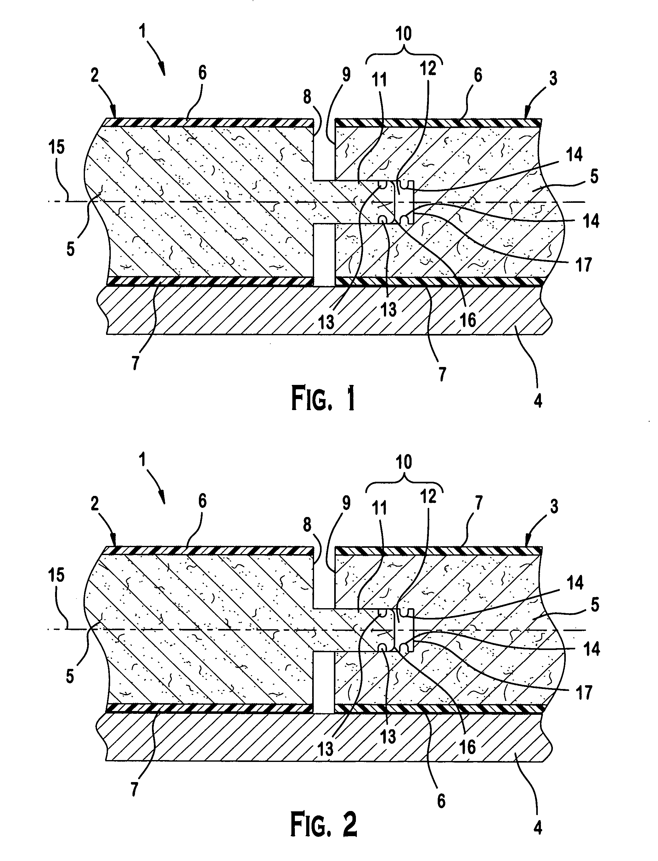
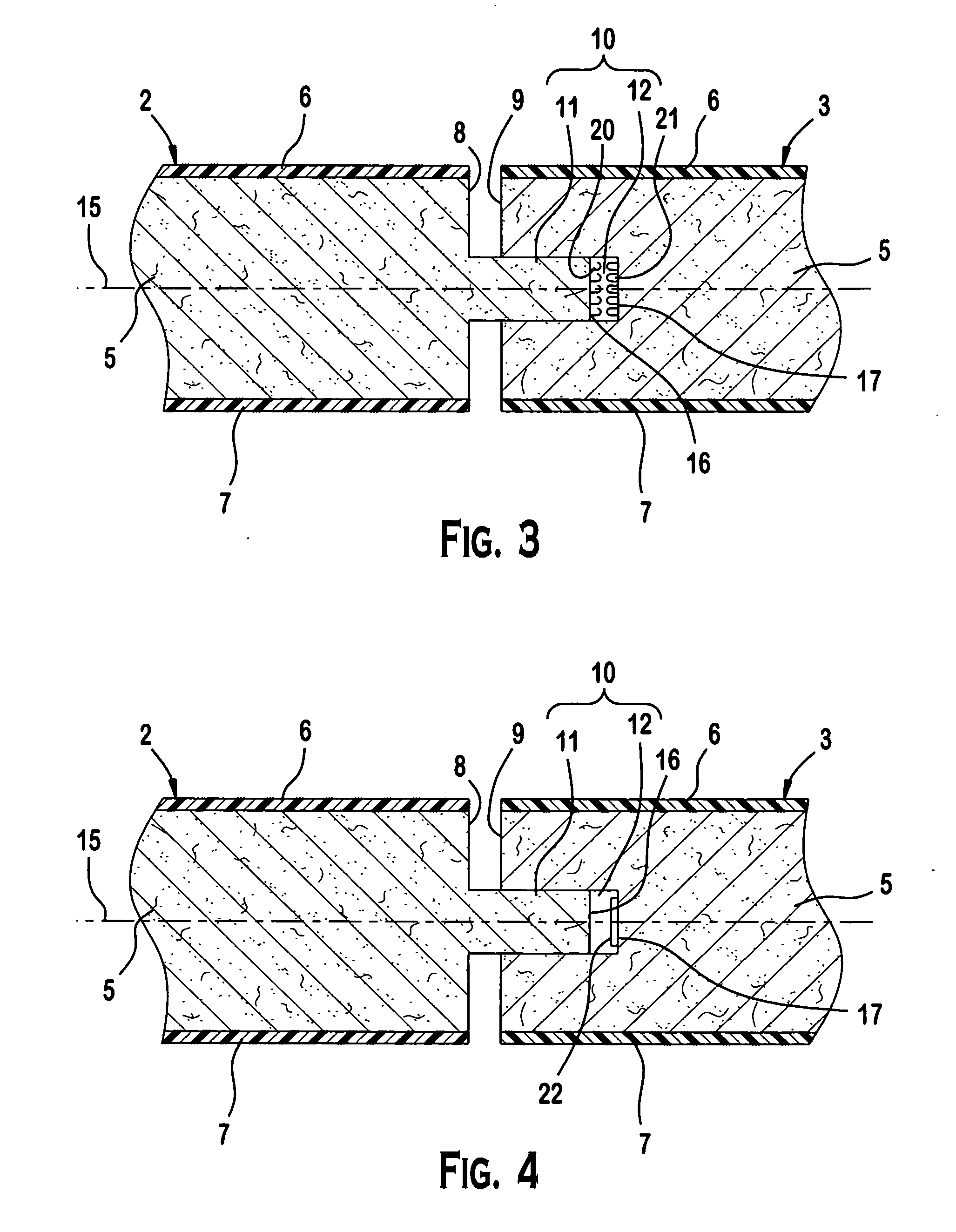
[0035]FIG. 1 shows a flooring system 1 including first and second flooring panels 2, 3 according to the invention. As shown in FIG. 1, the flooring system 1 consists of at least two of the first and second flooring panels 2, 3 mounted on a sub-floor 4. In the illustrated embodiment, the first and second flooring panels 2, 3 are identical and each consists of a core 5, a first decorative surface 6, a second decorative surface 7, and a locking member 10. The core 5 is interposed between the first and second decorative surfaces 6, 7. The core 5 may be, for example, a wood laminate core consisting of one or more layers of high density fiberboard or medium density fiberboard. The core 5 has opposing first and second side surfaces 8, 9 that extend substantially perpendicular to the first and second decorative surfaces 6, 7. The first decorative surface 6 opposes the second decorative surface 7 and extends substantially parallel thereto. The first and second decorative surfaces 6, 7 may co...
second embodiment
[0049]FIG. 15 shows a flooring system 40 including first and second flooring panels 41, 42 according to the invention. As shown in FIG. 15, the flooring system 40 consists of at least two of the first and second flooring panels 41, 42 mounted on a sub-floor 43. In the illustrated embodiment, the first and second flooring panels 41, 42 are identical and each consists of a core 44, a first decorative surface 45, a second decorative surface 46, and a locking member 50. The core 44 is interposed between the first and second decorative surfaces 45, 46. The core 44 may be, for example, a wood laminate core consisting of one or more layers of high density fiberboard or medium density fiberboard. The core 44 has opposing first and second side surfaces 47, 48 that extend substantially perpendicular to the first and second decorative surfaces 45, 46. The first decorative surface 45 opposes the second decorative surface 46 and extends substantially parallel thereto. The first and second decora...
third embodiment
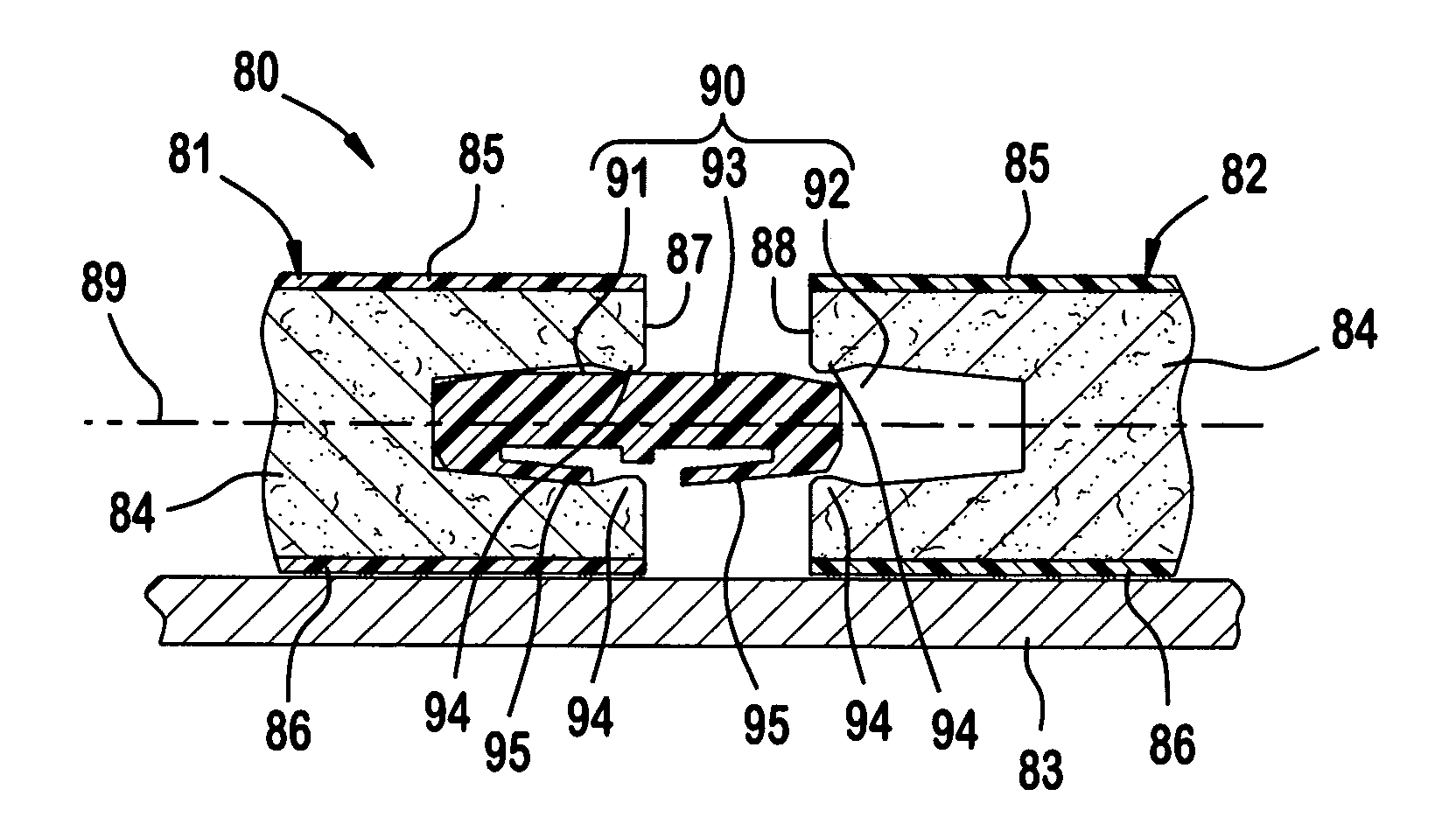
[0063]FIG. 26 shows a flooring system 80 including first and second flooring panels 81, 82 according to the invention. As shown in FIG. 26, the flooring system 80 consists of at least two of the first and second flooring panels 81, 82 mounted on a sub-floor 83. In the illustrated embodiment, the first and second flooring panels 81, 82 are identical and each consists of a core 84, a first decorative surface 85, a second decorative surface 86, and a locking member 90. The core 84 is interposed between the first and second decorative surfaces 85, 86. The core 84 may be, for example, a wood laminate core consisting of one or more layers of high density fiberboard or medium density fiberboard. The core 84 has opposing first and second side surfaces 87, 88 that extend substantially perpendicular to the first and second decorative surfaces 85, 86. The first decorative surface 85 opposes the second decorative surface 86 and extends substantially parallel thereto. The first and second decora...
PUM
 Abstract
Description
Claims
Application Information