Thermal bottle sock and associated methods

a technology of thermal insulation and bottle sock, which is applied in the field of thermal insulation bottle sock, can solve the problems of messy thermal elements, complex devices, and only serving to passively resist changes in temperature, and achieves the effect of straightforward us

Active Publication Date: 2010-04-22
FREE TO BE ME PROD
View PDF18 Cites 7 Cited by
  • Summary
  • Abstract
  • Description
  • Claims
  • Application Information

AI Technical Summary

Benefits of technology

[0005]In view of the foregoing background, an object of the present invention is to provide a thermal bottle sock that allows active heating of a fluid within a bottle for an extended period of time while being portable and relatively straightforward to use.

Problems solved by technology

Such a wrap, however, only serves to passively resist changes in temperature.
However, these devices require elaborate, often bulky structures and sometimes utilize potentially toxic and / or messy thermal elements.

Method used


Image

  • Thermal bottle sock and associated methods
  • Thermal bottle sock and associated methods
  • Thermal bottle sock and associated methods

Examples


Embodiment Construction

[0019]The present invention will now be described more fully hereinafter with reference to the accompanying drawings, in which preferred embodiments of the invention are shown. This invention may, however, be embodied in many different forms and should not be construed as limited to the embodiments set forth herein. Rather, these embodiments are provided so that this disclosure will be thorough and complete, and will fully convey the scope of the invention to those skilled in the art. Like numbers refer to like elements throughout, and prime and double prime notations are used to indicate similar elements in alternative embodiments.

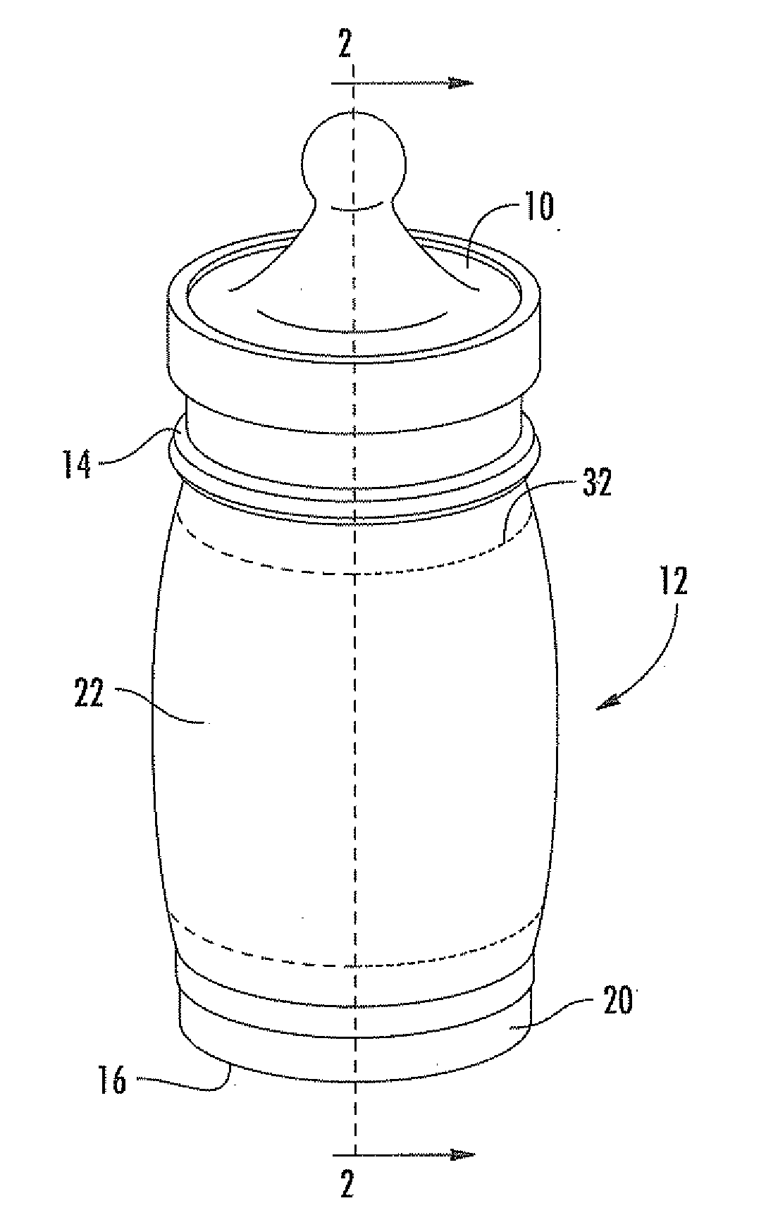
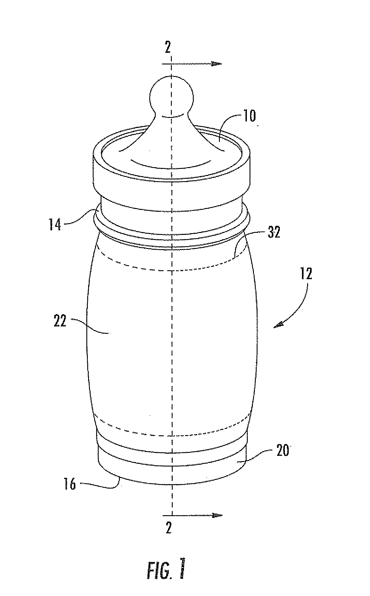
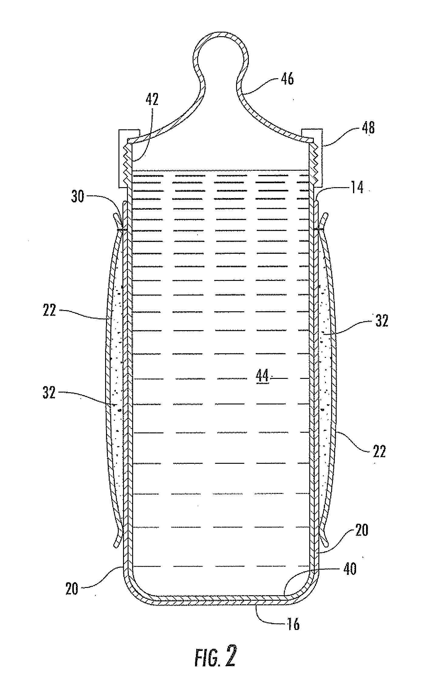
[0020]Referring to FIGS. 1 and 2, a bottle 10 is held by a thermal bottle sock 12. The thermal bottle sock 12 may also be referred to as a bottle warmer. The thermal bottle sock 12 extends between a first end 14 and a second end 16, and includes an inner sleeve 20 and an outer sleeve 22. The inner and outer sleeves 20, 22 are both connected to an elastic ...


PUM


Abstract

A bottle warmer includes a flexible tubular sleeve having a closed lower end and an open upper end. The open upper end is to receive a bottle therethough, and the closed lower end is to receive a bottom of the bottle thereagainst. An elastic band is carried by a medial portion of the flexible tubular sleeve to secure the medial portion to an adjacent portion of the bottle, and permit the open upper end to be folded back adjacent the closed lower end to define a pocket. A chemical heat source element is to be received by the pocket for warming the bottle.

Description

RELATED APPLICATIONS[0001]This application claims the benefit of U.S. Provisional Application Ser. No. 61 / 106,747 filed Oct. 20, 2008, the entire contents of which are incorporated herein by reference.FIELD OF THE INVENTION[0002]The present invention relates to thermal bottle holders, and more particularly, to a thermal bottle sock that heats a fluid within a bottle.BACKGROUND OF THE INVENTION[0003]Bottles are frequently used to transport a fluid for later use or consumption. While the fluid remains in the bottle, it is often desirable or even necessary to maintain the fluid at or near a desired temperature. Additionally, it may be desirable to keep the fluid initially at one temperature and then raise the fluid to a higher temperature before use or consumption. For example, if baby milk or formula stored in a bottle is to be brought on an outing, such as a picnic, it may be desirable that the bottle be kept cool to inhibit bacteria formation and / or growth, and then warmed to a desi...

Claims


Application Information

Patent Timeline
Patent Type & Authority Applications(United States)
IPC IPC(8): F24J1/00F24V30/00
CPCA47J36/2411F24J1/00A47J36/30B65D81/3876F24V30/00
Inventor CHRISTY, MAUREEN
Owner FREE TO BE ME PROD
Why Eureka
Try Eureka