Knife holder for a rotary disk cutterbar

a technology of rotary disk cutter and blade holder, which is applied in the field of rotary mowers, can solve the problems of premature wear of knife pin and/or knife, relatively frequent change of knives on rotary disk cutter bars,

Inactive Publication Date: 2010-04-29
DEERE & CO
View PDF14 Cites 38 Cited by
  • Summary
  • Abstract
  • Description
  • Claims
  • Application Information

AI Technical Summary

Benefits of technology

[0006]The invention in one form is directed to a rotary mower, including a rotary cutting disk, at least one knife, at least one knife pin, and a spring plate. The rotary cutting disk has at least one knife mount location. Each knife has an end with an opening therein. Each knife opening has a double keyhole shape with a larger center hole and two smaller partial holes respectively on generally opposite sides of the center hole. Each knife pin extends through a corresponding knife opening and is mounted to the rotary cutting disk at a corresponding knife mount location. Each knife pin has a distal keeper with a double keyhole shape which generally approximates and is slightly smaller than the double keyhole shaped opening in each knife. A spring plate is positioned under the cutting disk adjacent to each distal keeper of each knife pin.
[0007]The invention in another form is directed to a knife holder for a rotary disk cutterbar in a rotary mower. A knife has an end with an opening therein. The opening has a double keyhole shape with a larger center hole and two smaller partial holes respectively on generally opposite sides of the center hole. A knife pin is configured to be received within the knife opening and has a distal keeper with a double keyhole shape which generally approximates and is slightly smaller than the double keyhole shaped opening in the knife.
[0008]The invention in yet another form is directed to a knife holder for a rotary disk cutterbar in a rotary mower. A knife includes an end with a keyed opening therein. The keyed opening has a generally round hole and at least one adjoining keying feature. The knife pin is configured to be received within the keyed opening. The knife pin has a distal keeper with a keyed shape which generally approximates and is slightly smaller than the keyed opening in the knife.

Problems solved by technology

Changing knives on a rotary disk cutterbar may occur relatively frequently as a result of wear and impact damage.
The translational movement of the knife relative to the knife pin can cause premature wear of the knife pin and / or knife.

Method used


Image

  • Knife holder  for a rotary disk cutterbar
  • Knife holder  for a rotary disk cutterbar
  • Knife holder  for a rotary disk cutterbar

Examples


Embodiment Construction

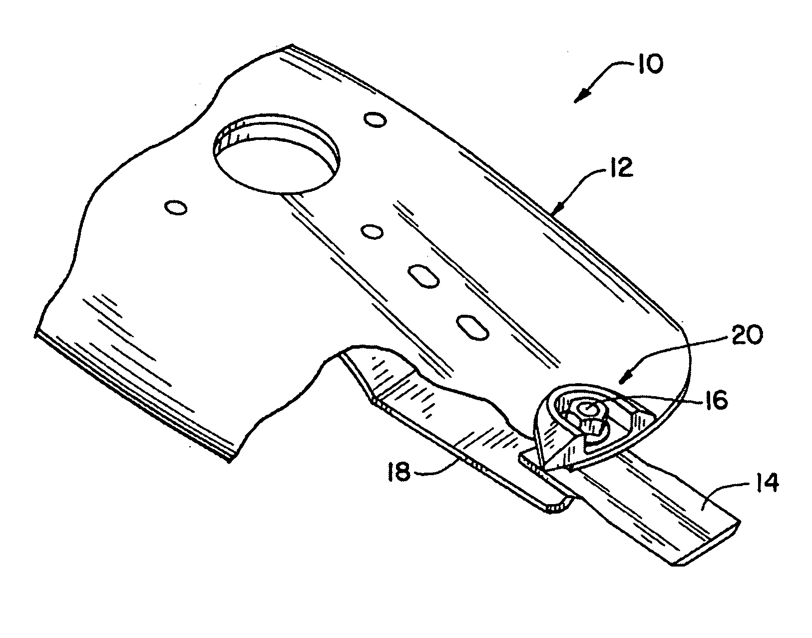
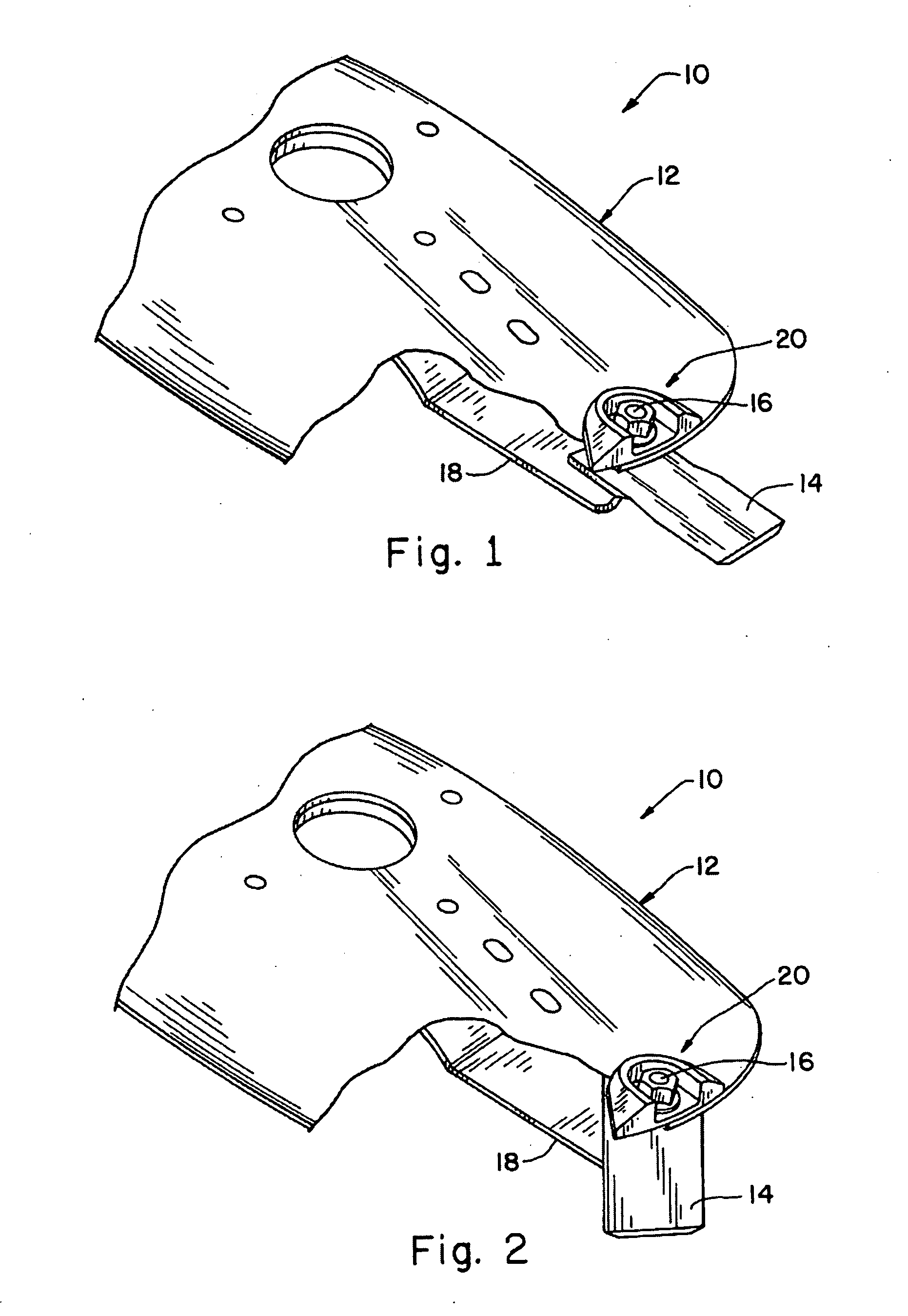
[0017]Referring now to the drawings, and more particularly to FIGS. 1-3, there is illustrated a portion of a rotary disk cutterbar 10 of the present invention. Rotary disk cutterbar 10 is one of a number of rotary disk cutterbars which are arranged along the leading edge of an agricultural mower / conditioner. The rotary disk cutterbars 10 may be modularly constructed, as shown, or non-modular in construction.

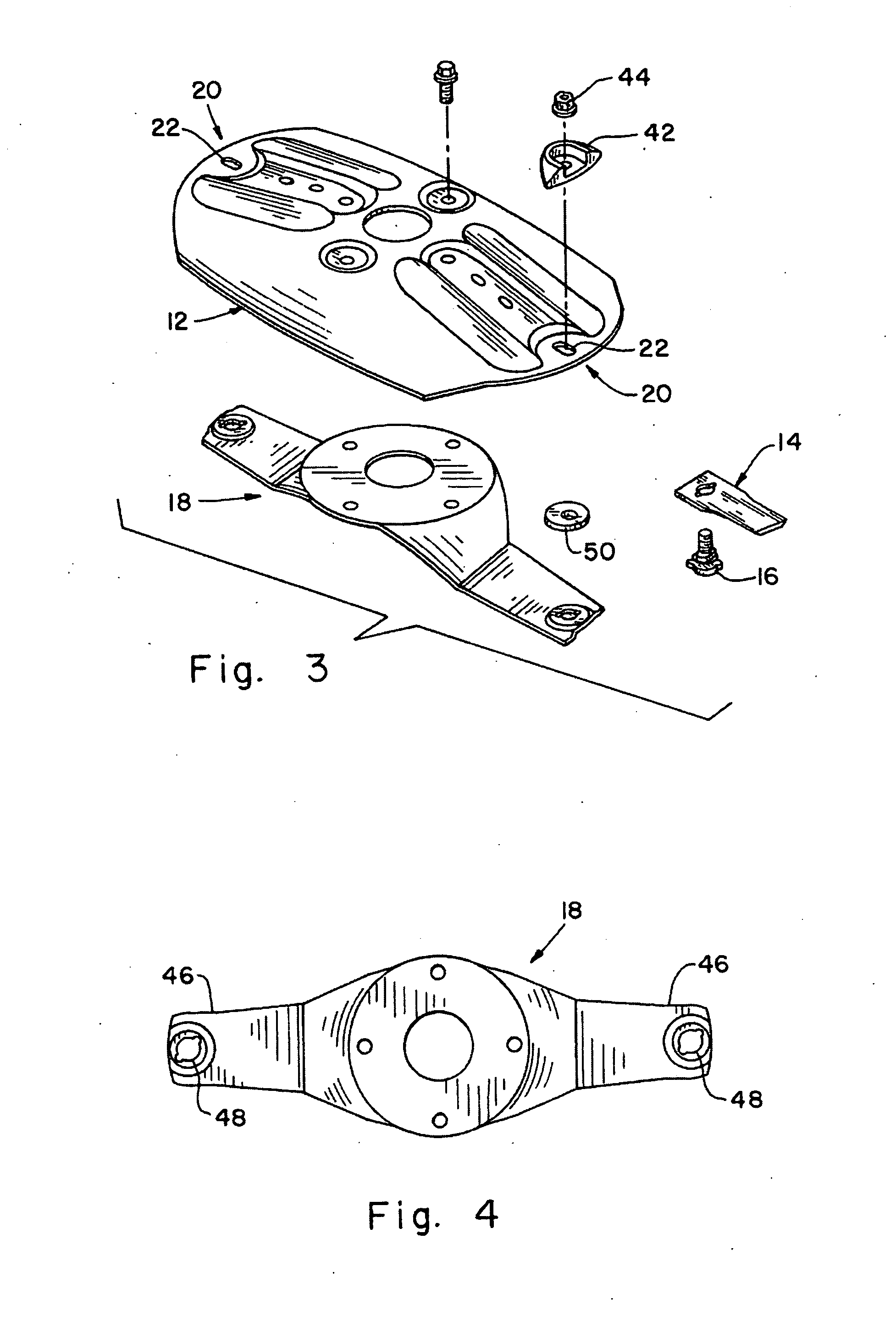
[0018]Rotary disk cutterbar 10 generally includes (in addition to other parts, not illustrated) a rotary cutting disk 12, at least one knife 14, at least one knife pin 16, and a spring plate 18. In the illustrated embodiment, rotary disk cutterbar 10 includes a pair of knives 14 and a corresponding pair of knife pins 16, positioned on generally opposite ends of cutting disk 12 (only one of which is shown for simplicity).

[0019]Rotary cutting disk 12 may be similar to or generally the same as rotary cutting disks which are currently used on rotary disk cutterbars manufactured and s...


PUM


Abstract

A rotary mower includes a rotary cutting disk, at least one knife, at least one knife pin, and a spring plate. The rotary cutting disk has at least one knife mount location. Each knife has an end with an opening therein. Each knife opening has a double keyhole shape with a larger center hole and two smaller partial holes respectively on generally opposite sides of the center hole. Each knife pin extends through a corresponding knife opening and is mounted to the rotary cutting disk at a corresponding knife mount location. Each knife pin has a distal keeper with a double keyhole shape which generally approximates and is slightly smaller than the double keyhole shaped opening in each knife. A spring plate is positioned under the cutting disk adjacent to each distal keeper of each knife pin.

Description

FIELD OF THE INVENTION [0001]The present invention relates to mowers, and, more particularly, to agricultural rotary mowers having multiple cutter heads.DESCRIPTION OF THE RELATED ART [0002]An agricultural mower is used for cutting vegetative matter such as hay or the like. The mower includes a cutterbar which cuts the vegetative matter at a predetermined distance from the ground. The cutterbar may be in the form of a sickle cutterbar or a rotary disk cutterbar. In the case of a rotary disk cutterbar, a common platform carries a plurality of cutterbar modules, with each cutterbar module including a large oval disk with free swinging knives which cut the crop (the disks may also be other than oval shaped, such as round or triangular). The oval disks are driven with a gear train carried within the platform in a timed manner such that the working width of adjacent disks overlap but do not interfere with each other. Examples of mowers using a rotary disk cutterbar include the model Nos....

Claims


Application Information

Patent Timeline
Patent Type & Authority Applications(United States)
IPC IPC(8): A01D34/73
CPCA01D34/733A01D34/736
Inventor YANKE, BRYAN RAY
Owner DEERE & CO
Why Eureka
Try Eureka